
Underfloor structure of automotive vehicle

a technology for automotive vehicles and underfloors, which is applied in the direction of vehicle body stabilisation, road transportation emission reduction, transportation and packaging, etc., can solve the problems of unavoidable leakage of air in engine rooms, and achieve the effect of reducing the air resistance of the vehicl

Active Publication Date: 2018-11-13
MAZDA MOTOR CORP
View PDF12 Cites 5 Cited by
  • Summary
  • Abstract
  • Description
  • Claims
  • Application Information

AI Technical Summary

Benefits of technology

[0005]An object of the present invention is to provide an underfloor structure of an automotive vehicle which can properly reduce the air (aerodynamic) resistance of the vehicle despite the above-described leakage of the air from the engine room.
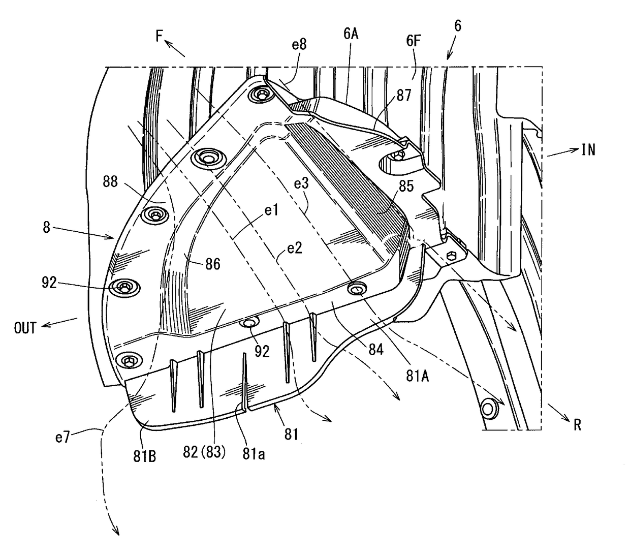
[0007]According to the present invention, in an area facing the front of the front wheel (i.e., at the position located so as to overlap the front wheel in the front view), the slant face portion of the deflector guides the traveling air in such a manner that the traveling air flows downward and then hits against the vertical wall portion, so that turbulence of the air overflowing the deflector can be made properly small, thereby reducing the air resistance which may be caused by this turbulence. Meanwhile, in another area which is located inward, in the vehicle width direction, from the above-described area facing the front of the front wheel (i.e., at the position located inward, in the vehicle width direction, from the above-described position located so as to overlap the front wheel in the front view), the traveling air which has been guided downward by the slant face portion of the deflector can easily flow over the vertical wall portion of the deflector, without generating any improperly-large turbulence, because the wall height of the vertical wall portion in this area is relatively small (i.e., the lower end portion of this part of the vertical wall portion is positioned at the higher level than the lower end portion of the above-described other part of the vertical wall portion located so as to overlap the front wheel in the front view). Consequently, this traveling air straightly flows rearward on the inward side, in the vehicle with direction, of the front wheel accommodated in the wheel house, without decreasing its flowing speed. A flowing speed of the air leaking out of an engine room is slower than that the above-described traveling air guided downward by the slant face portion, so that the air leaking out of the engine room is sucked to the traveling air guided downward by the slant face portion, thereby joining with this traveling air and then flowing rearward together with this traveling air. Accordingly, this air leaking out of the engine room can suppress occurring of an airflow flowing out from below the vehicle floor in back of the wheel house, so that any turbulence of an airflow which flows on a vehicle-body side face can be properly suppressed. As a result, reducing of the air resistance and suppressing of the turbulence can be compatibly achieved.
[0010]According to this embodiment, part of the traveling air flowing down in the area facing the front of the front wheel can be smoothly guided outward and then rearward by the curve-shaped outer wall.
[0012]According to this embodiment, the strength of the protrusion portion (against an impact from below or the like) can be properly improved.
[0014]According to this embodiment, since the above-described recess portion causes a decreased of a local pressure of the under-flower airflow, the above-described joined airflows of the traveling air guided downward by the slant face portion and the air leaking out of the engine room are drawn to this recess portion, so that this recess portion becomes a flow passage of the joined airflows. Accordingly, the above-described suppression of the occurrence of the airflow flowing out can be achieved surely.
[0015]Herein, it may be preferable that an outward side, in the vehicle width direction, of the recess portion is partitioned by a lower portion of a side sill extending in a vehicle longitudinal direction. Thereby, the above-described prevention of the airflow flowing out can be achieved more surely.

Problems solved by technology

This is a flow of the air in an engine room which unavoidably leaks out from a gap generated around a front suspension member.

Method used


Image

  • Underfloor structure of automotive vehicle
  • Underfloor structure of automotive vehicle
  • Underfloor structure of automotive vehicle

Examples


Embodiment Construction

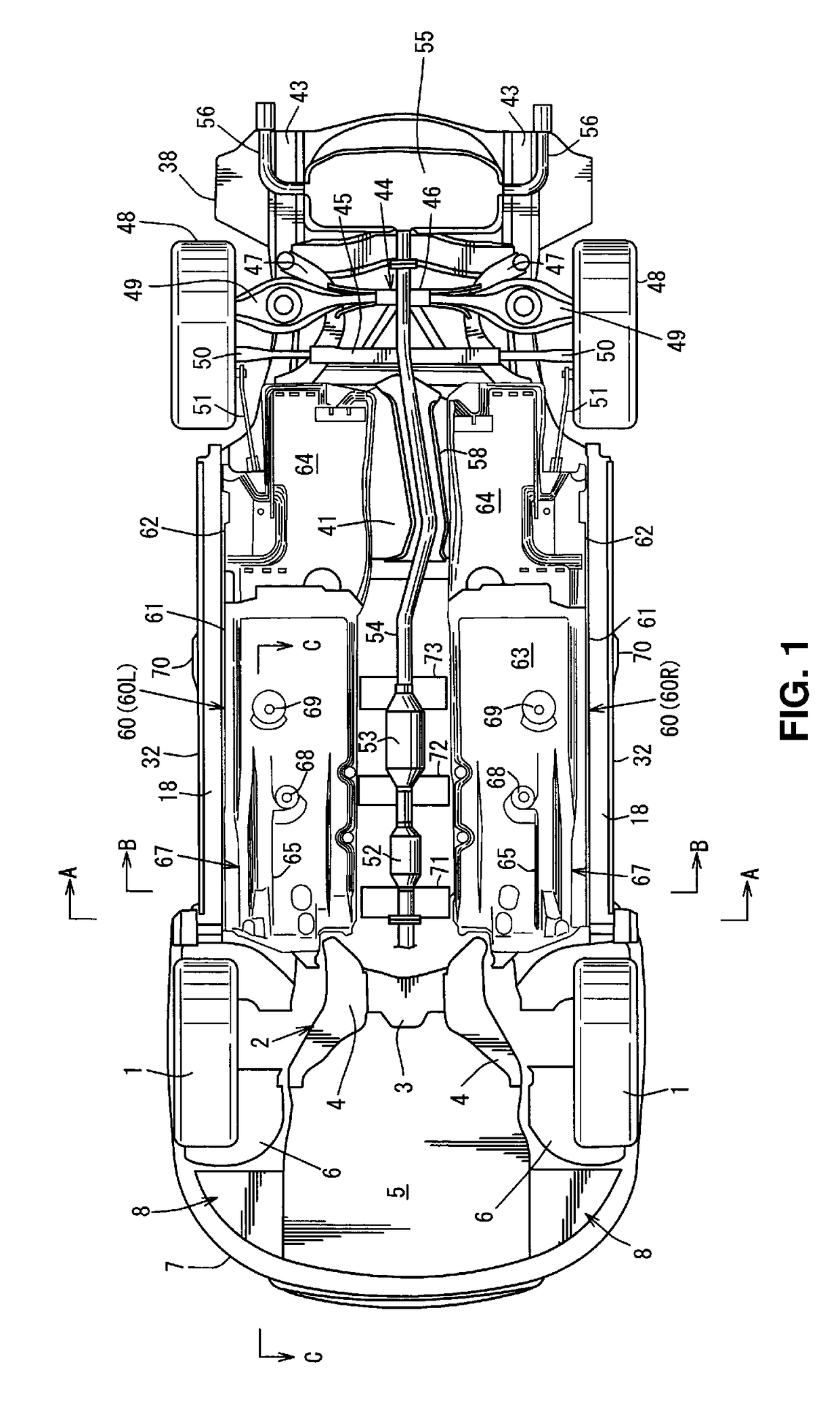
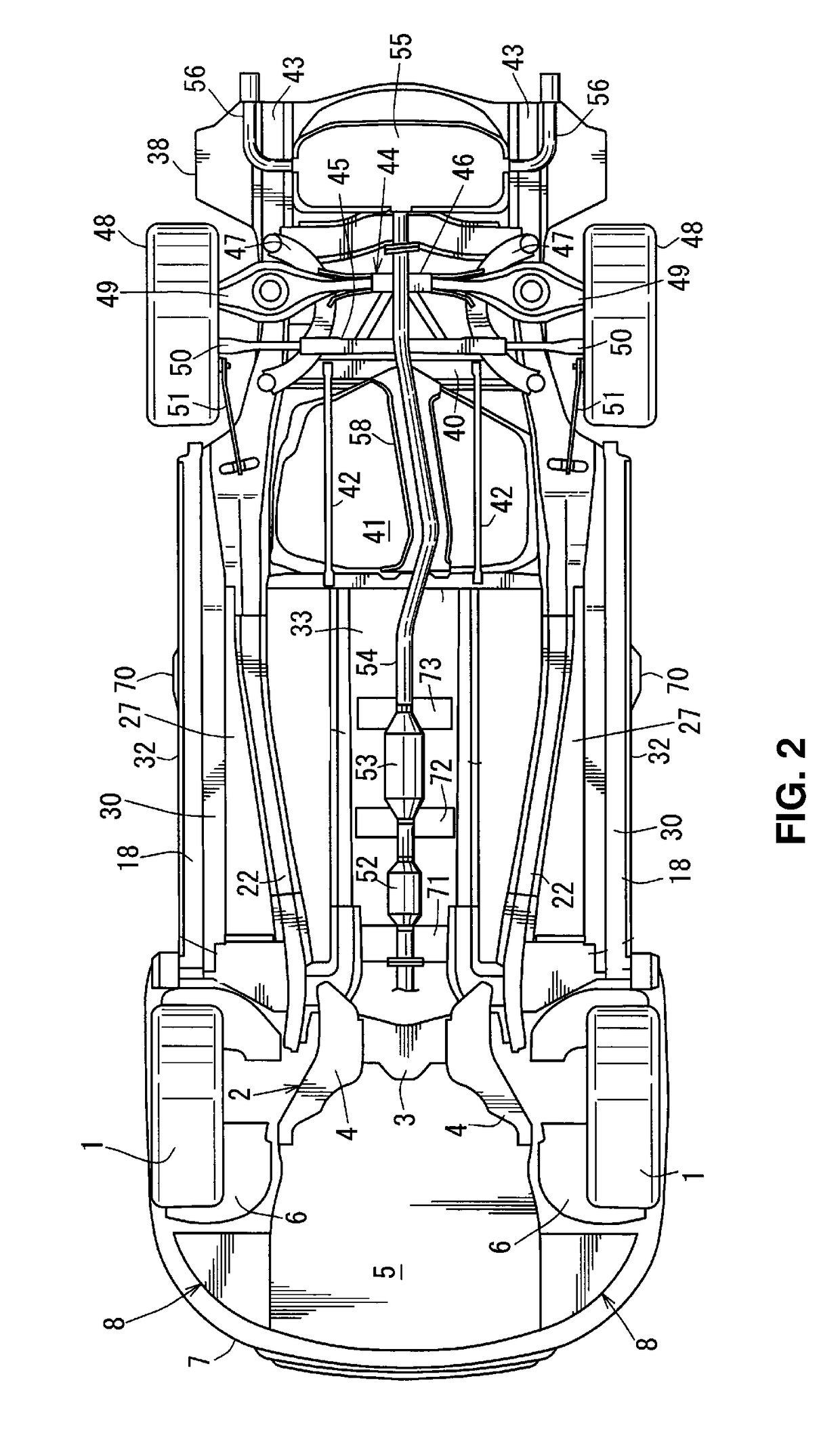
[0028]Hereafter, an embodiment of the present invention will be described specifically referring to the accompanying drawings. The drawings show an underfloor structure of an automotive vehicle, and FIG. 1 is a bottom view of the automotive vehicle provided with the present underfloor structure, FIG. 2 is a bottom view of the automotive vehicle in a state in which right-and-left undercovers are removed from a state shown in FIG. 1, FIG. 3 is a main-part sectional view taken along line A-A of FIG. 1, and FIG. 4 is a sectional view taken along line B-B of FIG. 1.

[0029]As shown in FIGS. 1 and 2, a sub frame 2 for mounting an engine and for attaching a front suspension to suspend a front wheel 1 is provided at a lower portion of an engine room. The sub frame 2 comprises a front cross member (not illustrated) which extends in a vehicle width direction at a front position, a rear cross member 3 which extends in the vehicle width direction at a rear position, and right-and-left side member...


PUM


Abstract

A deflector comprises a protrusion portion which protrudes downward, including a slant face portion slanting obliquely rearward and downward, and a vertical wall portion which is provided in back of the protrusion portion to extend in a vehicle width direction. A lower end portion of the vertical wall portion is positioned at a lower level than a rear end portion of the slant face portion. The lower end portion of part of the vertical wall portion located inward from the other part of the vertical wall portion located so as to overlap the front wheel in a front view is positioned at a higher level than the lower end portion of the other part of the vertical wall portion located so as to overlap the front wheel in the front view.

Description

BACKGROUND OF THE INVENTION[0001]The present invention relates to an underfloor structure of an automotive vehicle which comprises a deflector provided under a floor and in front of a front wheel.[0002]In general, it is known to regulate traveling air coming into a front wheel house by a deflector so as to reduce an airflow flowing out of the front wheel house toward a vehicle-body side face, thereby reducing the aerodynamic resistance of a vehicle (see European Patent Application Publication No. 1674381 A1).[0003]Herein, it is also known that a traveling-air guide is provided in front of the deflector in order to reduce the air resistance which is generated when the traveling air directly hits against a vertical wall of the deflector (see European Patent Application Publication No. 2607215 A2, for example).[0004]The inventors of the present invention have found that there still exits an airflow which flows out from below a vehicle floor near the front wheel house, thereby disturbin...

Claims


Application Information

Patent Timeline
Patent Type & Authority Patents(United States)
IPC IPC(8): B62D35/00B62D35/02B62D25/20B62D25/16
CPCB62D35/005B62D25/16B62D35/02B62D25/2036Y02T10/88B62D37/02
Inventor SHIBUTAKE, NOBUYUKINAKAYAMA, NOBUYUKIYOSHITAKE, KOJIKAWANO, AKIHIROABURAME, MASAFUMI
Owner MAZDA MOTOR CORP
Learn More