
Lens and method for enhanced visual targeting of a sports archery target

a sports archery and lens technology, applied in the field of eyewear, can solve the problems of eye fatigue, eye irritation, eye irritation, etc., and achieve the effect of low transmittance, high overall transmittance, and high transmittance through the lens

Active Publication Date: 2016-11-24
CARL ZEISS VISION ITAL SPA
View PDF2 Cites 0 Cited by
  • Summary
  • Abstract
  • Description
  • Claims
  • Application Information

AI Technical Summary

Benefits of technology

The patent describes a new type of eyewear for sports archery that reduces distraction and improves visual acquisition. The lens has a high overall transmittance in the spectral range, with a very low transmittance in certain color ranges that can negatively affect vision. The lens also has a specific color range with a low transmittance to help relax the athlete's eye. The eyewear also focuses the eye on the center of the target by reducing the visual field around the yellow center. This allows the athlete to see the target with clarity and focus on the center. The lens has a reduced value of red, which is the color of the target, and the target printing is manipulated to unbalance the two colors and enhance visual acquisition. The method includes using the eyewear for targeting or aiming at a sports archery target. Overall, this new eyewear improves the archer's ability to see and target the target with clarity.

Problems solved by technology

However, during long exhibitions and competitions, the eye of the athlete might become exhausted focusing the yellow center field.
Colors may become blurred, the eyes may become subject to tearing and visually aiming might be considered exhausting by the athlete.
This may all reduce concentration and the shooting routine and, hence, has a negative effect on the overall shooting performance.

Method used


Image

  • Lens and method for enhanced visual targeting of a sports archery target
  • Lens and method for enhanced visual targeting of a sports archery target
  • Lens and method for enhanced visual targeting of a sports archery target

Examples


Embodiment Construction

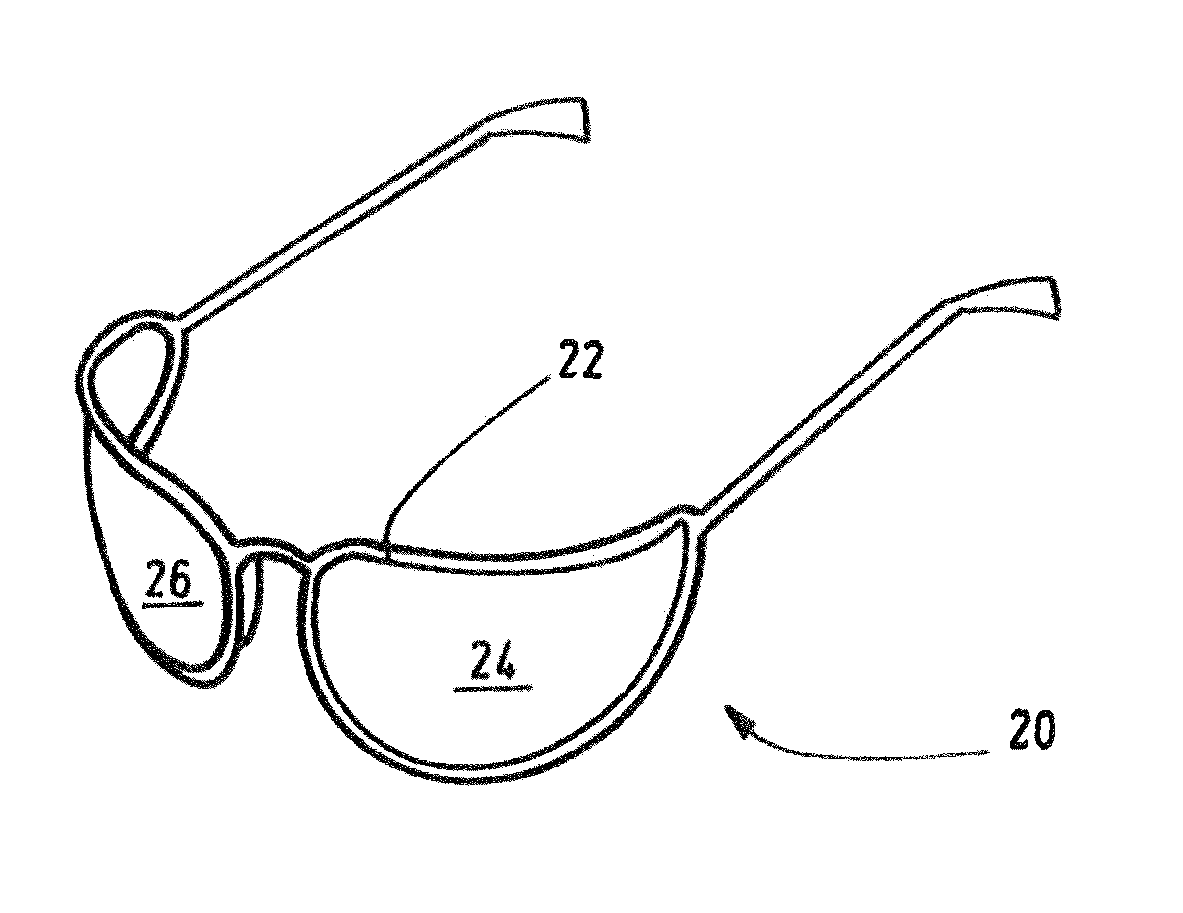
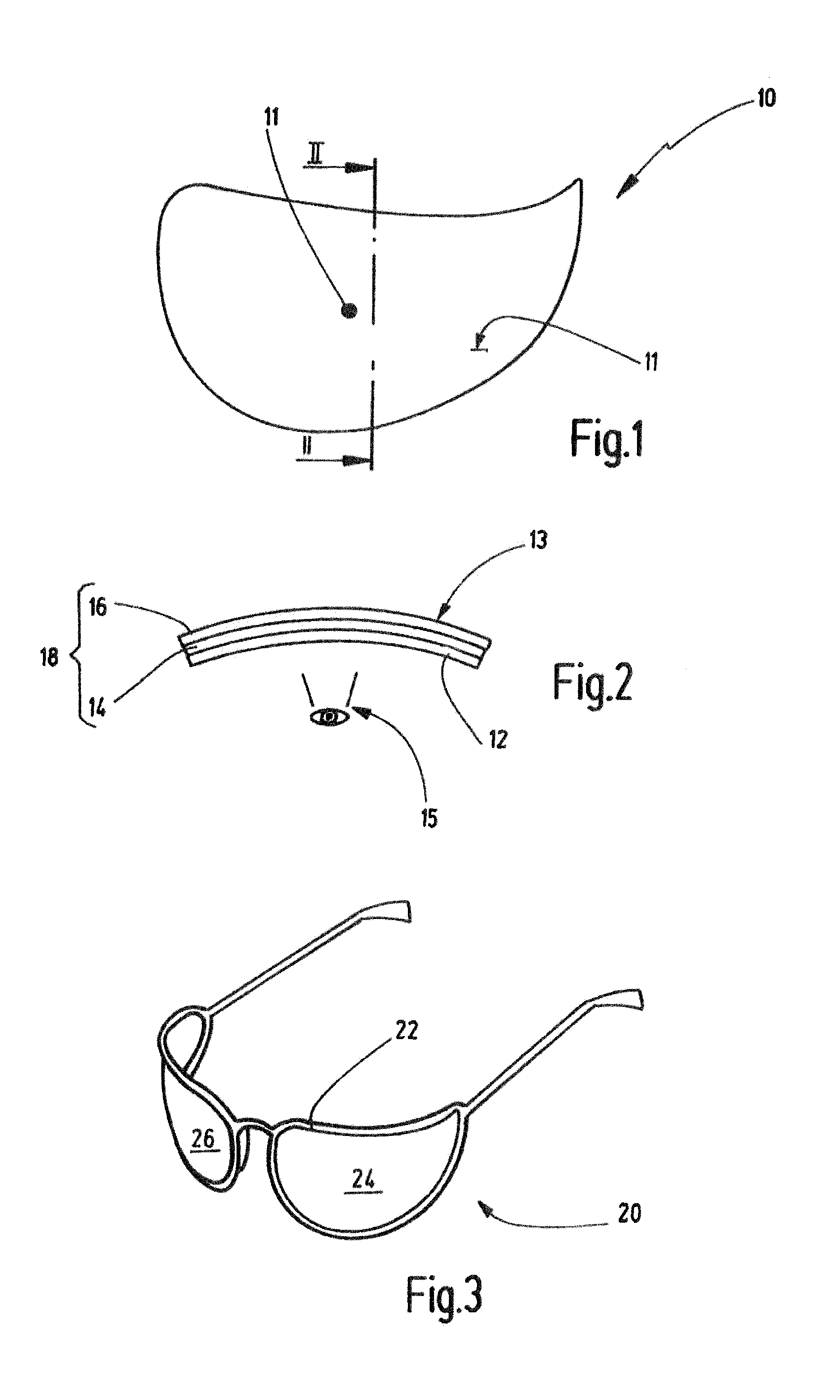
[0066]FIG. 1 shows an embodiment of a lens 10. The lens may have any desired shape, in general. The lens may provide for a correction according to a prescription. However, this may not necessarily be the case. In particular, it may be preferred that the lens 10 is a non-prescriptive lens. The lens has a center 11. The center 11 may be on an optical axis of the lens 10. In particular, the center may be the section point of the optical axis and the front surface 13 of the lens. As shown in FIG. 2, the front surface 13 is the surface of the lens 10 facing away from the eye 15 of a wearer during use. However, in particular in case the lens 10 should not have an optical axis, the center 11 may be at its boxed center, i.e. the intersection of the horizontal and vertical center lines in the boxing system or box system, in particular in case of an edged lens. Alternatively, it could be the geometrical center in case of a lens blank or uncut lens. For the corresponding definitions, reference...


PUM


Abstract

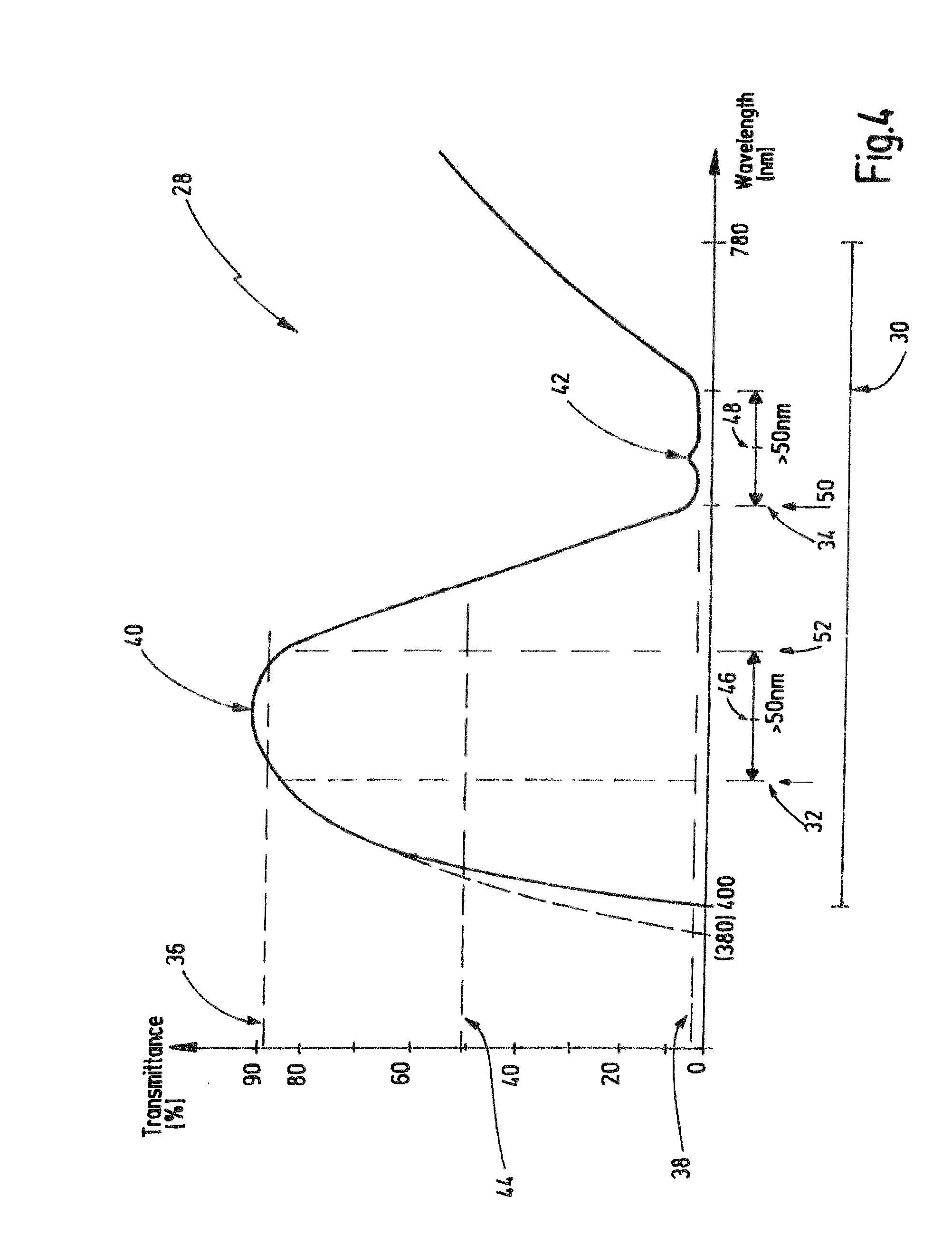
A lens for eyewear, the lens having a transmittance in a spectral range at least between 400 and 780 nm. The spectral range includes a first and a second color range which are different from each other. The first and second color ranges are each at least 50 nm broad. A first medium transmittance in the first range is higher than a second medium transmittance in the second range. A medium transmittance in the spectral range is above 35%. A maximum transmittance value in the spectral range is above 70%. The second medium transmittance is below 20%. A maximum value of transmittance within the second range is below 30%. The first medium transmittance is at least 15% higher than the second medium transmittance. Further, a method for providing a lens for eyewear for sports archery is provided. In particular, this may enhance visually targeting a sports archery target.

Description

CROSS-REFERENCE TO RELATED APPLICATION[0001]This is a Continuation application of International patent application PCT / US2014 / 014158, filed Jan. 31, 2014, the entire content of which is incorporated herein by reference.BACKGROUND OF THE INVENTION[0002]The current invention is directed to a lens for an eyewear, the lens having a transmittance in a spectral range at least between 400 and 780 nm, in particular between 400 and 780 nm or between 380 and 780 nm, wherein the spectral range includes a first color range and a second color range which are different from each other, wherein the first color range is at least 50 nm broad, wherein the second color range is at least 50 nm broad, wherein a first medium transmittance in the first color range is higher than a second medium transmittance in the second color range.[0003]According to a further aspect of the current invention, a method for providing a lens for an eyewear for sports archery is also provided. According to yet a further asp...

Claims


Application Information

Patent Timeline
Patent Type & Authority Applications(United States)
IPC IPC(8): G02C7/10F41J3/00
CPCF41J3/0004G02C7/104G02B5/223G02C7/02G02C7/06
Inventor PILLA, PHILIPPILLA, CARLOMALNATI, SABRINADISCONZI, MASSIMILIANO
Owner CARL ZEISS VISION ITAL SPA
Learn More