Safety Helmet Liner Impact Reducing Technology

a safety helmet and impact reduction technology, applied in the field of wearable protective equipment, can solve the problems of unusually heavy helmets for bicycle riding applications

Inactive Publication Date: 2016-12-01
DVORAK PAUL WILLIAM
View PDF23 Cites 8 Cited by
  • Summary
  • Abstract
  • Description
  • Claims
  • Application Information

AI Technical Summary

Problems solved by technology

The Snell Foundation had introduced the first bicycle helmet standard in the United States in 1970, but at the time only a...

Method used


Image

  • Safety Helmet Liner Impact Reducing Technology
  • Safety Helmet Liner Impact Reducing Technology
  • Safety Helmet Liner Impact Reducing Technology

Examples


embodiments 1-2

[0044]In the following descriptions, like reference characters designate like or corresponding parts throughout the several views and embodiments. Also, it is to be understood that such terms as “forward,”“rearward,”“left,”“right,”“upwardly,”“downwardly,” and the like are words of convenience and are not to be construed as limiting terms. Locations, shapes, sizes, materials, numbers, relative positions, angular positions, velocities of motion, ranges of motion, electrical tolerances, mechanical tolerances, and other such properties of the devices within the embodiments may be altered and are not to be construed as limiting factors. Nor should the components comprising an assembly be construed as the only suggested components within that assembly.

[0045]Referring now to the drawings, it will be understood that the illustrations are for the purpose of describing embodiments of the invention and are not intended to limit the invention thereto.

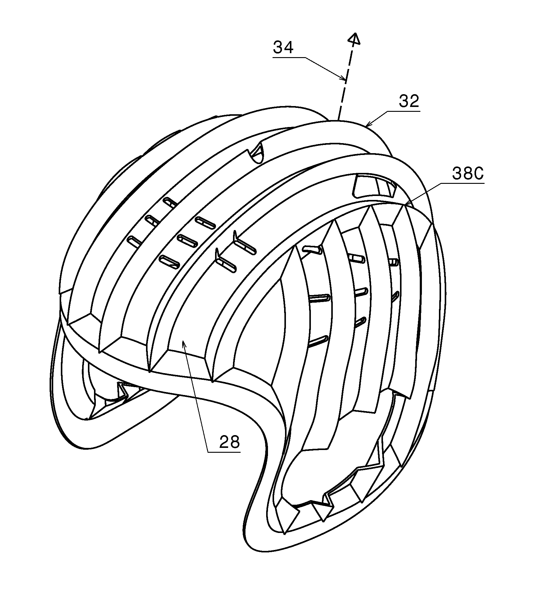
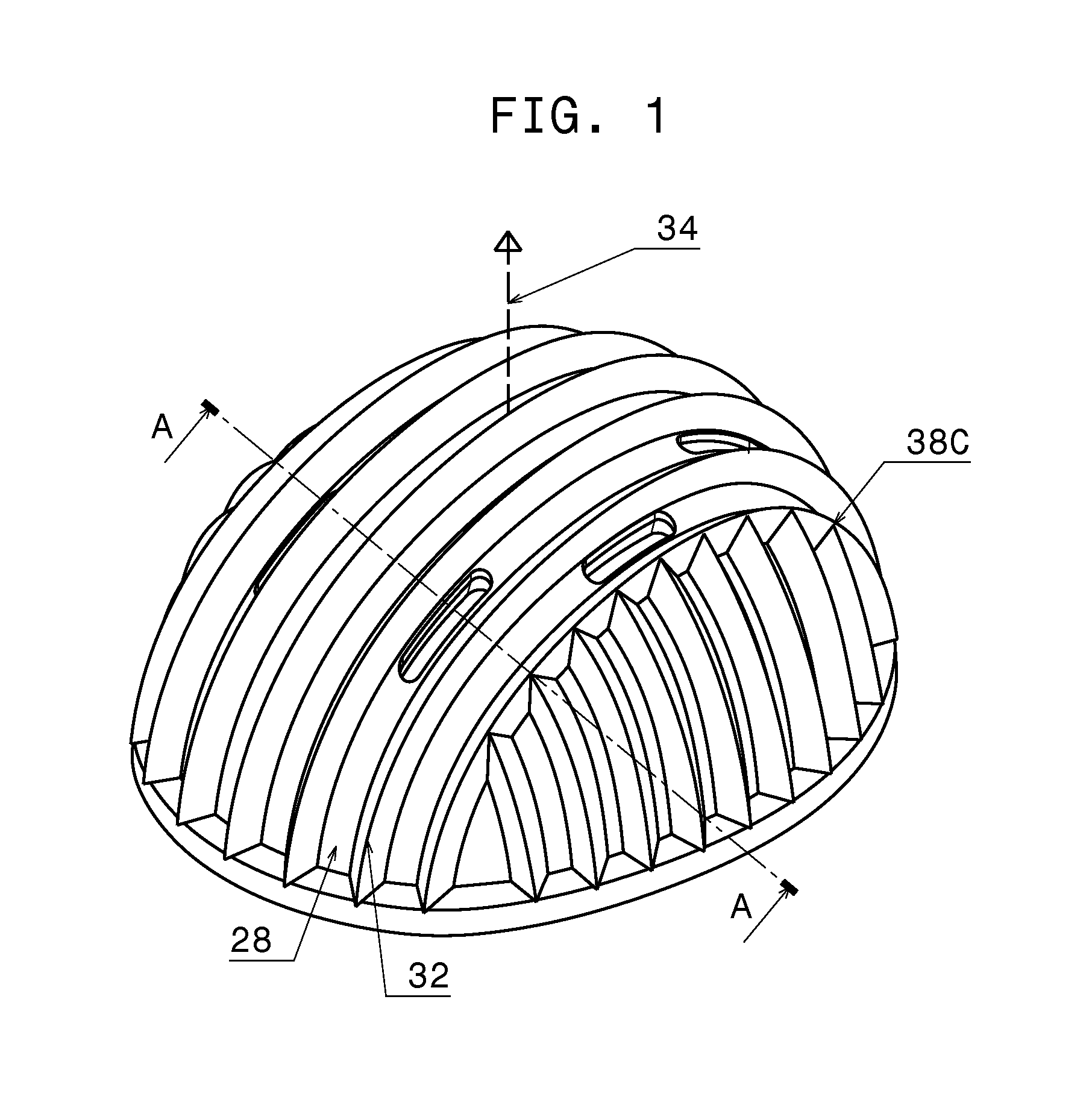
[0046]FIG. 1 is a perspective view from abov...


PUM

PropertyMeasurementUnit
Flexibilityaaaaaaaaaa

Abstract

An article of headwear includes an inner liner 20, a corrugated shell 24, and an outer shell 26. An impact to headwear causes the corrugated shell to elastically deform, with the shell then returning to its original shape. An arrangement of the corrugations allows ease of manufacturing on a vacuum form or injection mold.

Description

CROSS-REFERENCE TO RELATED APPLICATIONS[0001]This application claims the benefit of PPA Ser. Nr. U.S. patent application Ser. No. 61 / 997,222, filed 2014 May 27 by the present inventor, which is incorporated by reference.FEDERALLY SPONSORED RESEARCH[0002]Not applicableSEQUENCE LISTING OR PROGRAM[0003]Not applicableBACKGROUND[0004]1. Field of Invention[0005]This invention relates to wearable protective equipment, specifically to helmets and other shells intended to reduce the effect of impacts.[0006]2. Prior Art[0007]Helmets are known to have existed for almost 3000 years. Originally they were made of bronze, iron and leather to protect soldiers in battle. Over time, they evolved to protect people in a variety of fields, including construction, firefighting, and a variety of sports. In each application, designers have had to meet specific demands, but the general goal has always been to protect the head against blunt or pointed impacts.[0008]In the past century, helmets have seen impr...

Claims


Application Information

Patent Timeline
IPC IPC(8): A42B3/12B29C51/10B29C45/40A42B3/06
CPCA42B3/124A42B3/06B29L2031/4807B29C45/40B29C51/10B29C45/14688B29C51/16B29L2031/4821
Inventor DVORAK, PAUL WILLIAM
Owner DVORAK PAUL WILLIAM
Why Eureka
Try Eureka