
Annular barrier having a downhole expandable tubular

a tubular, annular technology, applied in the direction of borehole/well accessories, heat treatment equipment, furnaces, etc., can solve the problems of insufficient welding of the ends of the expandable sleeve the limited annular space surrounding the annular barrier, and the inability to mount the expandable sleeve. to the base pipe, so as to prevent free expansion

Active Publication Date: 2016-12-01
WELLTEC OILFIELD SOLUTIONS AG
View PDF4 Cites 8 Cited by
  • Summary
  • Abstract
  • Description
  • Claims
  • Application Information

AI Technical Summary

Benefits of technology

This patent describes an improved expandable tubular and an improved annular barrier for use in oil and gas drilling operations. The expanded annular barrier can provide isolation between two zones without the need for additional parts that prevent free expansion. The design of the annular barrier is slim, allowing it to fit into smaller boreholes, and can be easily submerged. These technical improvements make the process of drilling oil and gas wells more efficient and reliable.

Problems solved by technology

In some wells, the annular space surrounding the annular barrier is so limited that the expandable sleeve cannot be mounted by means of connection sleeve parts surrounding the expandable sleeve to fasten the expandable sleeve to the base pipe.
A mere welding of the ends of the expandable sleeve to the base pipe does not suffice, since tests have shown that there is a risk that the expandable sleeve will rupture or depart from the base pipe.

Method used


Image

  • Annular barrier having a downhole expandable tubular
  • Annular barrier having a downhole expandable tubular
  • Annular barrier having a downhole expandable tubular

Examples


Embodiment Construction

[0074]The present technology is described in relation to several non-limiting examples, aspects of which may be combined with one another.

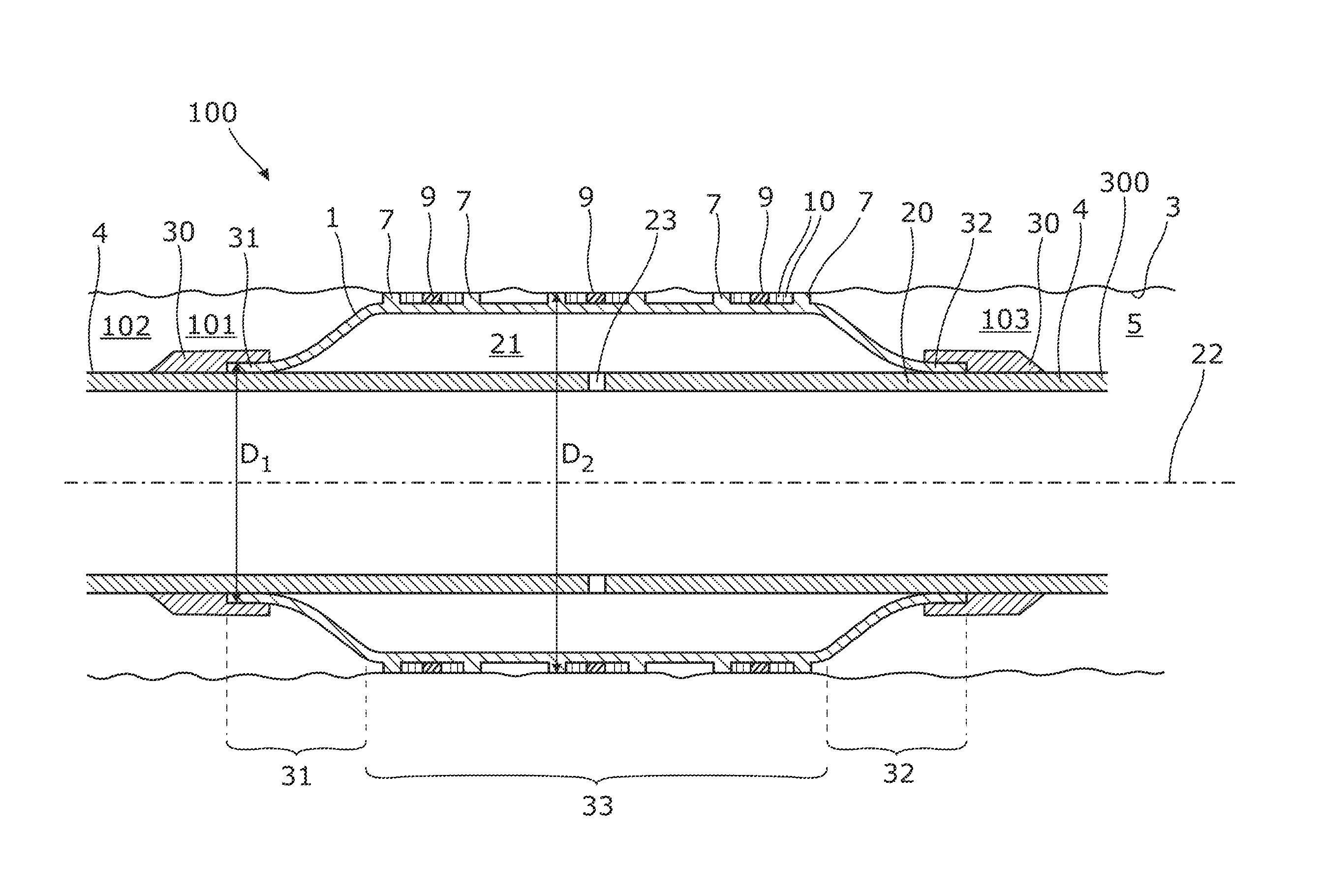
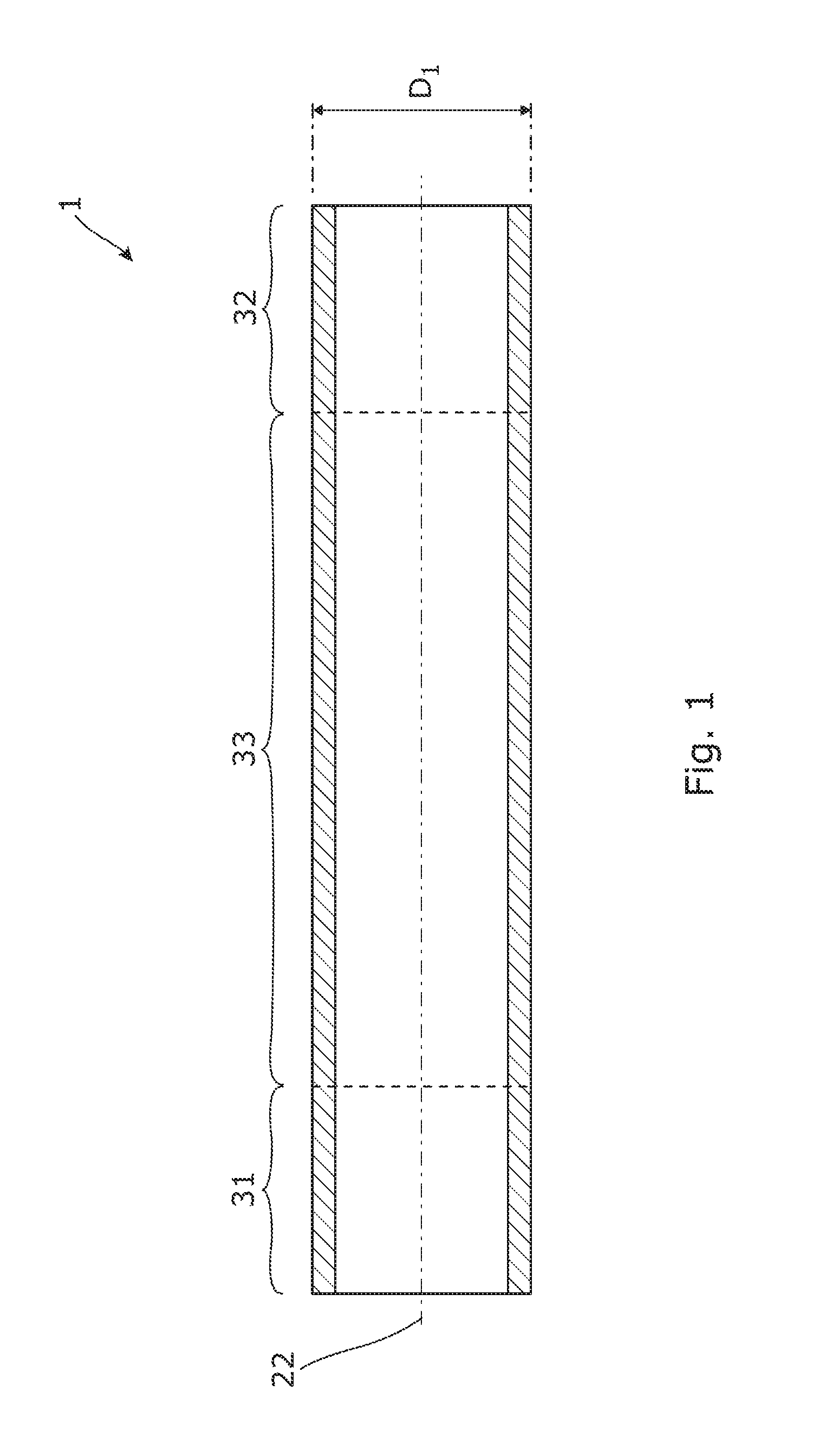
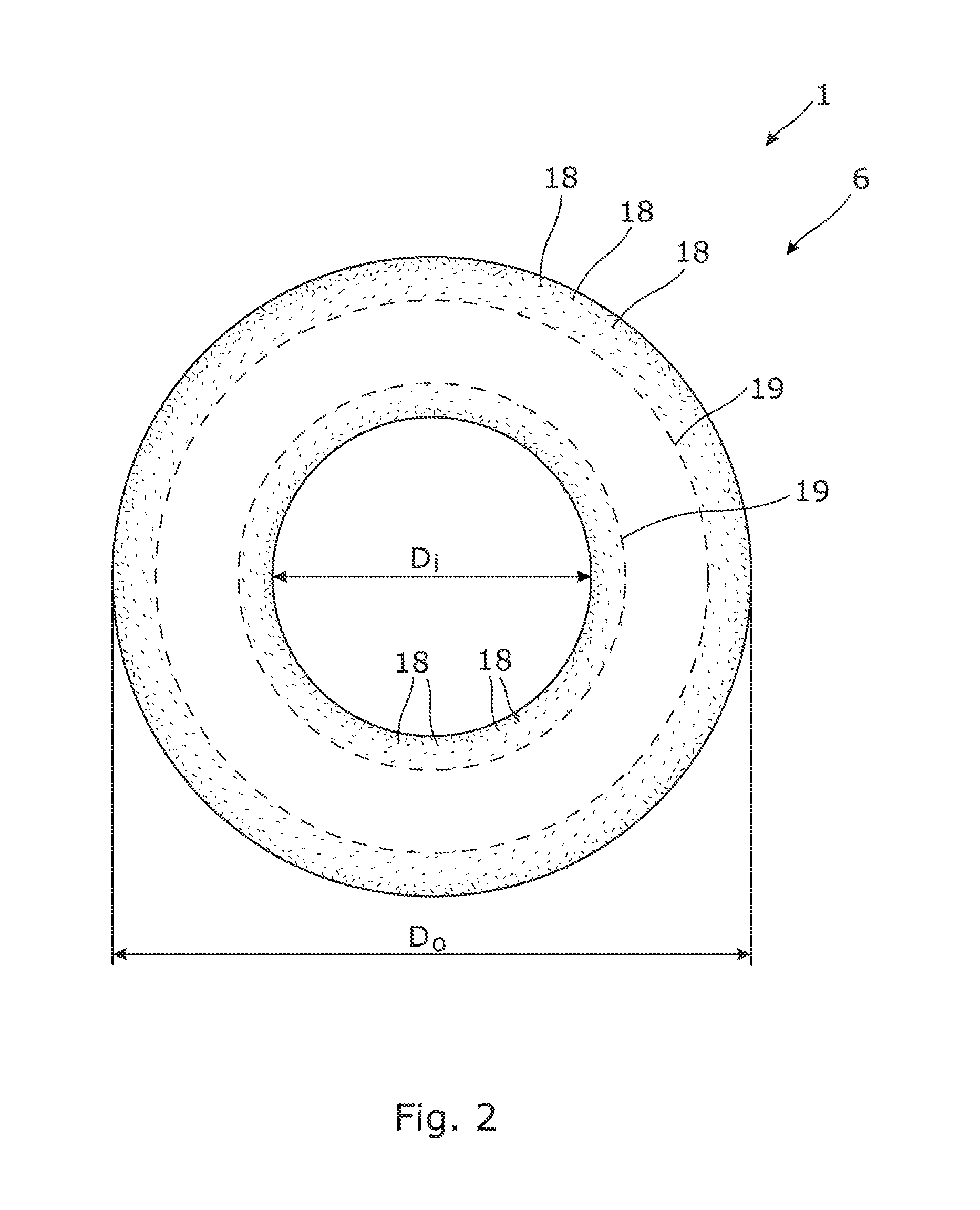
[0075]FIG. 1 shows a cross-sectional view of a downhole expandable tubular 1 to be at least partly expanded in a well 2 (as shown in FIG. 5) downhole from a first outer diameter D1 to a second outer diameter D2 (shown in FIGS. 6 and 12) to abut against an inner face of a casing or borehole. The downhole expandable tubular extends along a longitudinal axis 22, and along the axis, the downhole expandable tubular has a first end section 31, a second end section 32, and an intermediate section 33 between the first end section and the second end section. The downhole expandable tubular 1 is made from one metal tubular blank 6 (shown in FIG. 2) of one metal material, e.g. is a one piece construction made from a homogeneous metal material, as seen in cross section, including the end sections and the intermediate section. The metal material of the blank h...


PUM

PropertyMeasurementUnit
yield strengthaaaaaaaaaa
temperatureaaaaaaaaaa

Abstract

An annular barrier has a tubular part, and a downhole expandable tubular to be expanded in an annulus downhole from a first outer diameter to a second outer diameter to abut against an inner face of a casing or borehole. The downhole expandable tubular has a first end section, a second end section and an intermediate section between the first end section and the second end section, the downhole expandable tubular surrounding the tubular part. Each end section of the downhole expandable tubular is connected with the tubular part and extends along a longitudinal axis, and defines an annular barrier space between the tubular part and the downhole expandable tubular. The tubular is made from one metal tubular blank of one metal material, the metal material of the end sections having a higher yield strength than the metal material of the intermediate section.

Description

CROSS-REFERENCE[0001]This application claims priority to EP Patent Application No. 15169291.0 filed on 26 May 2015 and EP Patent Application No. 15173632.9 filed on 24 Jun. 2015, the entire contents of each of which are hereby incorporated by reference.FIELD OF THE TECHNOLOGY[0002]The present technology relates to an annular barrier to be expanded in an annulus between a well tubular structure and an inside face of a casing or borehole downhole for providing zone isolation between a first zone and a second zone of the casing or borehole. The present technology furthermore relates to an annular barrier to be expanded in an annulus, to a downhole completion system and to a manufacturing method for the manufacture of the downhole expandable tubular according to the present invention.BACKGROUND ART[0003]In some completions, annular barriers are often used for providing zone isolation, i.e. isolation of production zones from non-producing zones. The annular barriers are mounted as part o...

Claims


Application Information

Patent Timeline
Patent Type & Authority Applications(United States)
IPC IPC(8): E21B33/127C21D8/10C21D9/00
CPCE21B33/1277C21D8/105C21D9/0068E21B33/127
Inventor VASQUES, RICARDO REVESMASSEY, DEAN RICHARD
Owner WELLTEC OILFIELD SOLUTIONS AG
Learn More