
A lighting system and a method of controlling a lighting system

a lighting system and lighting technology, applied in the field of lighting systems, can solve the problem of still using a relatively large amount of energy, and achieve the effect of reducing power consumption, saving costs, and facilitating the operation of lighting systems

Inactive Publication Date: 2016-12-01
SIGNIFY HLDG BV
View PDF0 Cites 4 Cited by
  • Summary
  • Abstract
  • Description
  • Claims
  • Application Information

AI Technical Summary

Benefits of technology

The patent text describes a lighting system that uses efficiency information to control different light emitters, resulting in more efficient lighting and reduced power consumption. This system can also adjust the amount of light emitted based on the required minimum lighting conditions and the knowledge of the efficiency ratios between received light and power provided to the light emitters. The invention also includes a method to achieve the same benefits as the lighting system. The technical effect of this patent text is to provide a more efficient and cost-saving lighting system that optimizes the use of power and minimizes energy consumption.

Problems solved by technology

When the system of the published patent application is used, it still uses a relatively large amount of energy.

Method used


Image

  • A lighting system and a method of controlling a lighting system
  • A lighting system and a method of controlling a lighting system
  • A lighting system and a method of controlling a lighting system

Examples


Embodiment Construction

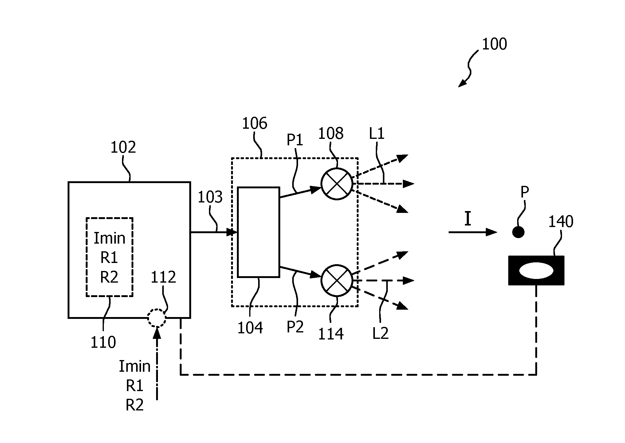
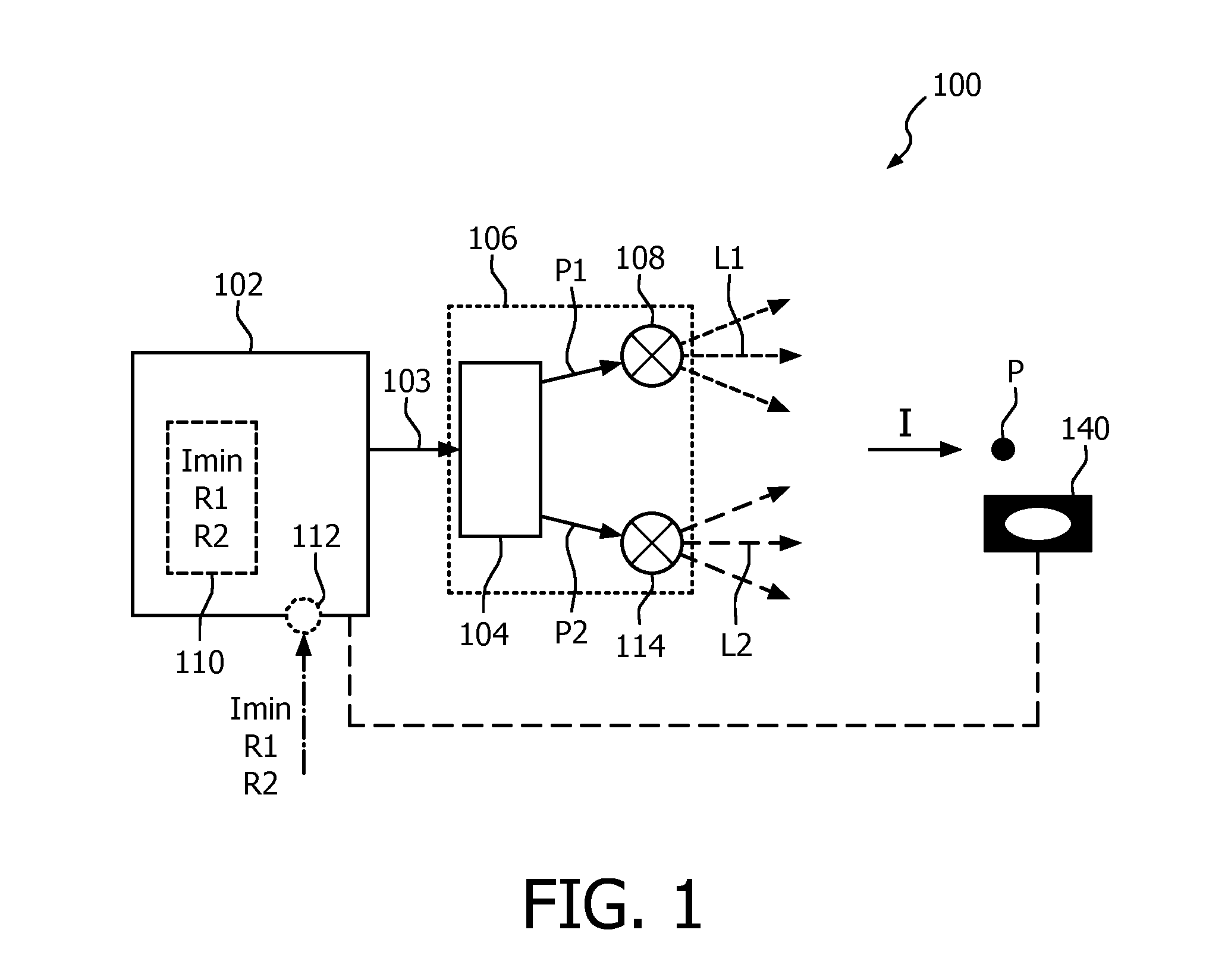
[0033]A first embodiment is shown in FIG. 1. FIG. 1 schematically shows an embodiment of a lighting system 100 which comprises a controller 102 and a lighting arrangement 106. The lighting arrangement 106 comprises a driving circuitry 104, a first light emitter 108 and a second light emitter 114. The driving circuitry 104 is coupled to the controller 102 and receives from the controller 102 a control signal 103. The driving circuitry 104 provides power P1, P2 to the first light emitter 108 and the second light emitter 114, respectively, to drive the light emitters 108, 114. The amount of provided power P1, P2 is determined by information being present in the control signal 103.

[0034]The first light emitter 108 emits light L1 of a first color distribution and the second light emitter 114 emits light L2 of a second color distribution. The second color distribution is different from the first color distribution and at least the human naked eye experiences a color difference between the...


PUM


Abstract

A lighting system 100 and a method of controlling a lighting system are provided. The lighting system comprises a lighting arrangement 106 with a first light emitter 108, a second light emitter 114 and a driving circuitry 104 and comprises a controller 102 providing a control signal 103 to the driving circuitry. The first and second light emitters emit different colors or light L1, L2. The controller is configured to generate the control signal such that a required minimum amount of light is received at a relative position P with respect to the lighting arrangement and that the amount of power used by the lighting arrangement is minimized when the lighting arrangement emits light in accordance with the generated control signal. In the generation of the control signal efficiency ratios R1, R2 for the different light emitters are taken in to account.

Description

FIELD OF THE INVENTION[0001]The invention relates to lighting systems which comprises at least two light emitters that emit different colors of light.[0002]The invention further relates to a method of controlling a lighting system.BACKGROUND OF THE INVENTION[0003]Today many lamps and lighting systems comprise several light emitters that emit light at different colors and such lamps and lighting systems may be controlled to emit the different colors of light in any possible combination such that about every color of light or about every spectral distribution of light may be emitted. Such lamps or lighting systems are often used to illuminate shelves in a shop or to illuminate a specific object. The lamps of the lighting system may be controlled such that presented products on the shelves or the object appears more appealing to humans. For example, when tomatoes in a supermarket are illuminated with light which comprise a relatively large amount of red light, buyers experience them as...

Claims


Application Information

Patent Timeline
Patent Type & Authority Applications(United States)
IPC IPC(8): H05B37/02H05B33/08F21K9/64H05B44/00
CPCH05B37/0227H05B37/0218F21K9/64F21Y2115/10H05B33/0866H05B37/0272H05B33/0851H05B45/20Y02B20/40H05B47/19H05B47/105H05B45/24H05B47/11
Inventor BAAIJENS, JOHANNES PETRUS WILHELMUSVAN HOOF, WILLEM PIET
Owner SIGNIFY HLDG BV
Learn More