Internal combustion engine
a combustion engine and combustion chamber technology, applied in the direction of machines/engines, electrical control, separation processes, etc., can solve the problems of increasing the amount of consumption of post-treatment use fuel, and decreasing the amount of consumption of combustion use fuel, so as to reduce the total amount of fuel used
- Summary
- Abstract
- Description
- Claims
- Application Information
AI Technical Summary
Benefits of technology
Problems solved by technology
Method used
Image

Examples
Embodiment Construction
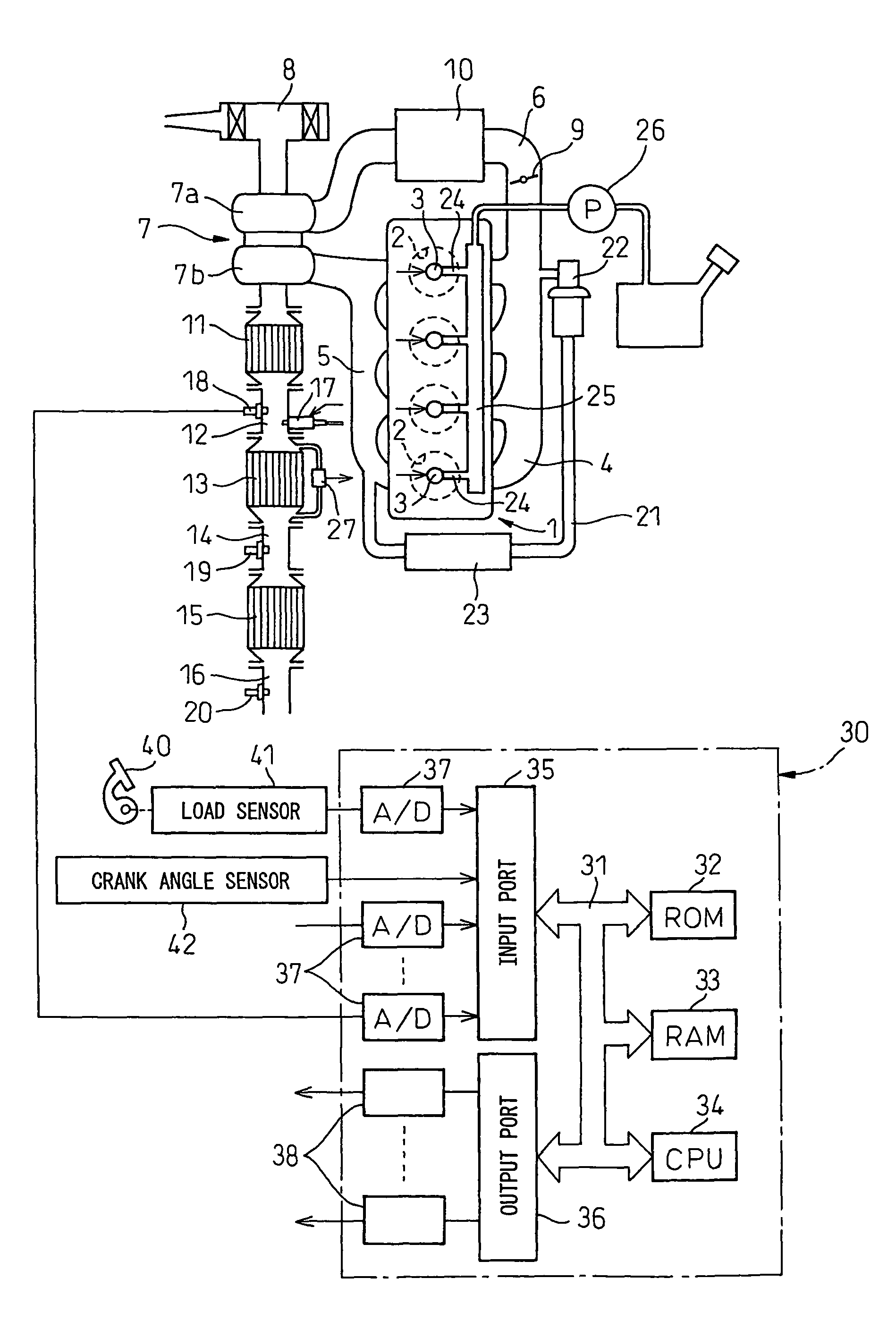
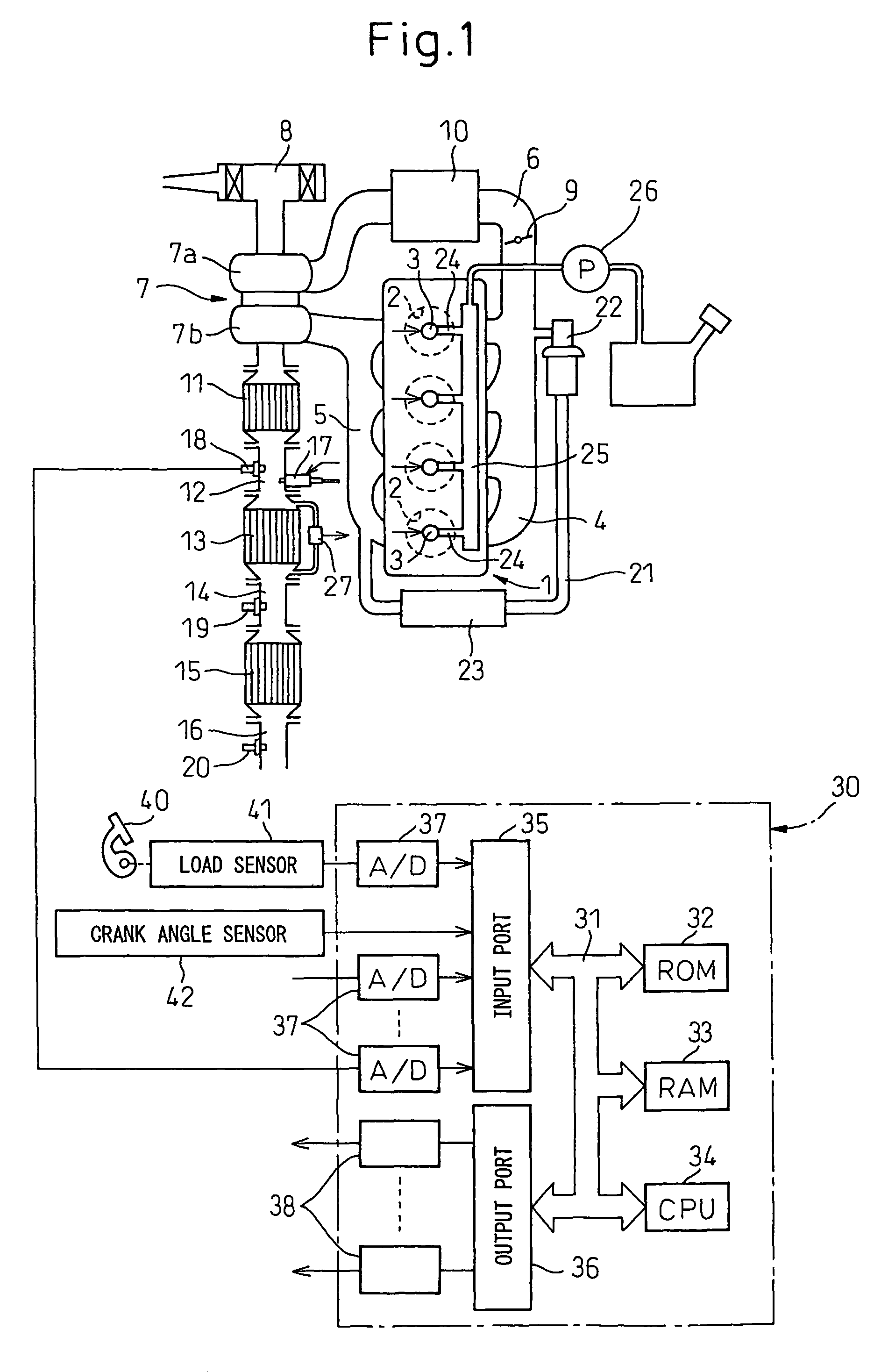
[0009]FIG. 1 shows an overview of a compression ignition type internal combustion engine.
[0010]Referring to FIG. 1, 1 indicates an engine body, 2 a combustion chamber of a cylinder, 3 an electronic control type fuel injector for injecting fuel into the combustion chamber 2, 4 an intake manifold, and 5 an exhaust manifold. The intake manifold 4 is connected via an intake duct 6 to an outlet of a compressor 7a of an exhaust turbocharger 7, while an inlet of the compressor 7a is connected to an air cleaner 8. The intake duct 6 has a throttle valve 9 driven by a step motor arranged inside it. Further, around the intake duct 6, a cooling system 10 for cooling the intake air flowing through the inside of the intake duct 6 is arranged. In the embodiment shown in FIG. 1, the engine cooling water is led into the cooling system 10 where the engine cooling water cools the intake air.
[0011]On the other hand, the exhaust manifold 5 is connected to an inlet of the exhaust turbine 7b of the exhaus...
PUM
 Abstract
Description
Claims
Application Information