Image guided radiotherapy

a radiotherapy and guided technology, applied in radiation therapy, x-ray/gamma-ray/particle irradiation therapy, radiation therapy, etc., can solve the problems of imposing a significant cost on the apparatus, redundant axis, and reducing the volume of the table and its supporting structur

Active Publication Date: 2016-12-08
ELEKTA AB
View PDF6 Cites 2 Cited by
  • Summary
  • Abstract
  • Description
  • Claims
  • Application Information

AI Technical Summary

Benefits of technology

[0010]The control means can determine the rotation r by obtaining a further image of the patient using the imaging device. The further image can be a CT scan, or an MRI scan, or an ultrasound scan, or can be a visual image of the patient. The control means can then determine the rotation r by comparing the image and the further image such

Problems solved by technology

A table with 6 degrees of freedom imposes a significant cost on the apparatus, and inevitably has a redundant axis.
The provision for multiple degrees of freedom also adds to the volume of the table and its supporting structure, which can give clearance problems during treatment.
It is also inherently undesirable to rotate the patient on the table, at least around horizontal axes

Method used


Image

  • Image guided radiotherapy
  • Image guided radiotherapy
  • Image guided radiotherapy

Examples


Embodiment Construction

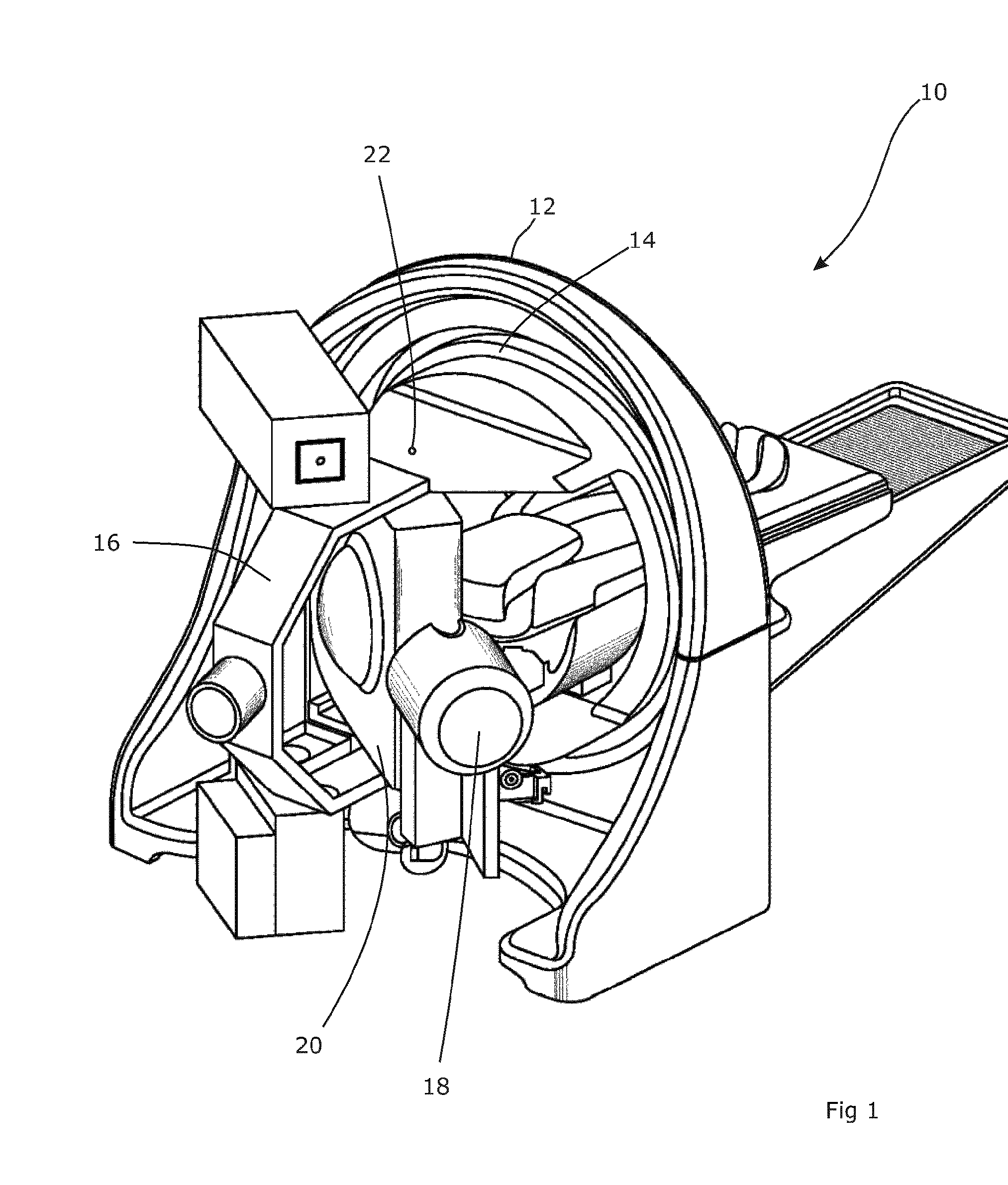
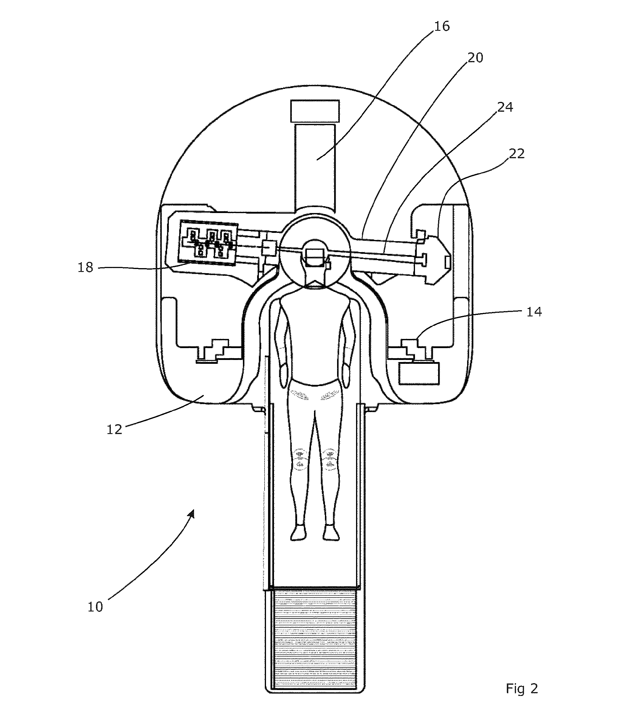
[0019]FIG. 1 illustrates the radiotherapy apparatus described in WO2005 / 041774, to which the reader is referred for a fuller description. In brief, the apparatus 10 comprises a substantial vertical circular outer ring structure 12 which is rigidly fixed to a floor structure in order to provide a firm base. An inner ring 14 is journalled within the outer ring 12 so that it can rotate about a horizontal axis, transverse to the outer ring 12 and passing through the centre of the circular ring. A U-profile support 16 is attached at either end to the inner ring 14 and extends out of the plane of the inner ring 14.

[0020]A linear accelerator 18 is supported on a mounting 20 that is carried by the U-profile support 16. The mounting 20 is attached to the support 16 via a pair of pivot connections 22, defined on opposing arms of the U-profile support 16 that extend out of the plane of the inner ring 14. These allow the mounting 20 to rotate relative to the support 16 about an axis that is per...


PUM


Abstract

An apparatus is disclosed, which comprises a radiotherapy delivery apparatus having a radiation source for emitting a beam of radiation and rotatable around an axis intersecting the beam through a range of at least x degrees, an imaging device, and a control unit for controlling the source and imaging device. The apparatus further comprises a treatment planning computer configured to receive a first image of a patient, and receive parameters defining the operations of the radiotherapy delivery apparatus. The parameters include an available range of rotation for the source defined as x-e, where e>0. The treatment planning computer is further configured to generate a treatment plan for the patient based on the received image and parameters. The control unit determines a patient position using the imaging device, determines a rotation r of the patient around the axis relative to the first image, and compensates for the rotation by offsetting the source by a rotation equal to r when r<e.

Description

FIELD OF THE INVENTION[0001]The present invention relates to image guided radiotherapy.BACKGROUND ART[0002]Radiotherapy is a process for the treatment of lesions such as cancers, which involves directing a beam of ionising radiation (typically high-energy x-rays) towards the lesion. Care is taken to maximise the dose that is applied to the lesion and minimise the dose that is applied to the areas of healthy tissue around the lesion, mainly by directing the beam toward the lesion from a multitude of directions and collimating the beam (i.e. shaping its cross-section) as required depending on the shape of the lesion. Various protocols exist for determining the beam directions, shapes, strengths and times to deliver a specific three-dimensional dose distribution to a specific region of the patient.[0003]Clearly, it is necessary to ensure that the dose distribution is positioned correctly within the patient, i.e. that the patient and the radiotherapy apparatus are correctly aligned. To ...

Claims


Application Information

Patent Timeline
IPC IPC(8): A61N5/10
CPCA61N5/1082A61N5/103A61N2005/1061A61N5/1049A61N5/1067A61N5/1065
Inventor CARLSSON, PER
Owner ELEKTA AB
Why Eureka
Try Eureka