Optics of projecor

Inactive Publication Date: 2016-12-08
ISHII FUSAO
View PDF15 Cites 20 Cited by
  • Summary
  • Abstract
  • Description
  • Claims
  • Application Information

AI Technical Summary

Benefits of technology

[0012]Another aspect of this invention is to reduce the speckle (which means the non-uniformity of brightness distribution of image) coming from laser light source. It was found that the interference is taking

Problems solved by technology

Conventional projectors use either Mercury lamp or LED which have wider spectrum and ha

Method used


Image

  • Optics of projecor
  • Optics of projecor
  • Optics of projecor

Examples


Embodiment Construction

[0074]FIG.-17 illustrates an example of the embodiment of this invention to make a laser light source suitable for projection displays, wherein laser diodes (1701 through 1705) are placed and fixed with solder or inorganic adhesive on a substrate (1706) and DOE or HOE (1708) is placed in front of the laser diodes and the DOE (or HOE) focuses the laser beams for the diodes to an optical fiber (1710) to integrate multiple laser beams into a single beam.

[0075]FIG.-18 illustrates another example of the embodiment of this invention to make a laser light source suitable for projection displays with an optical fiber having a funnel shaped edge so that it will provide more tolerance for misalignment.

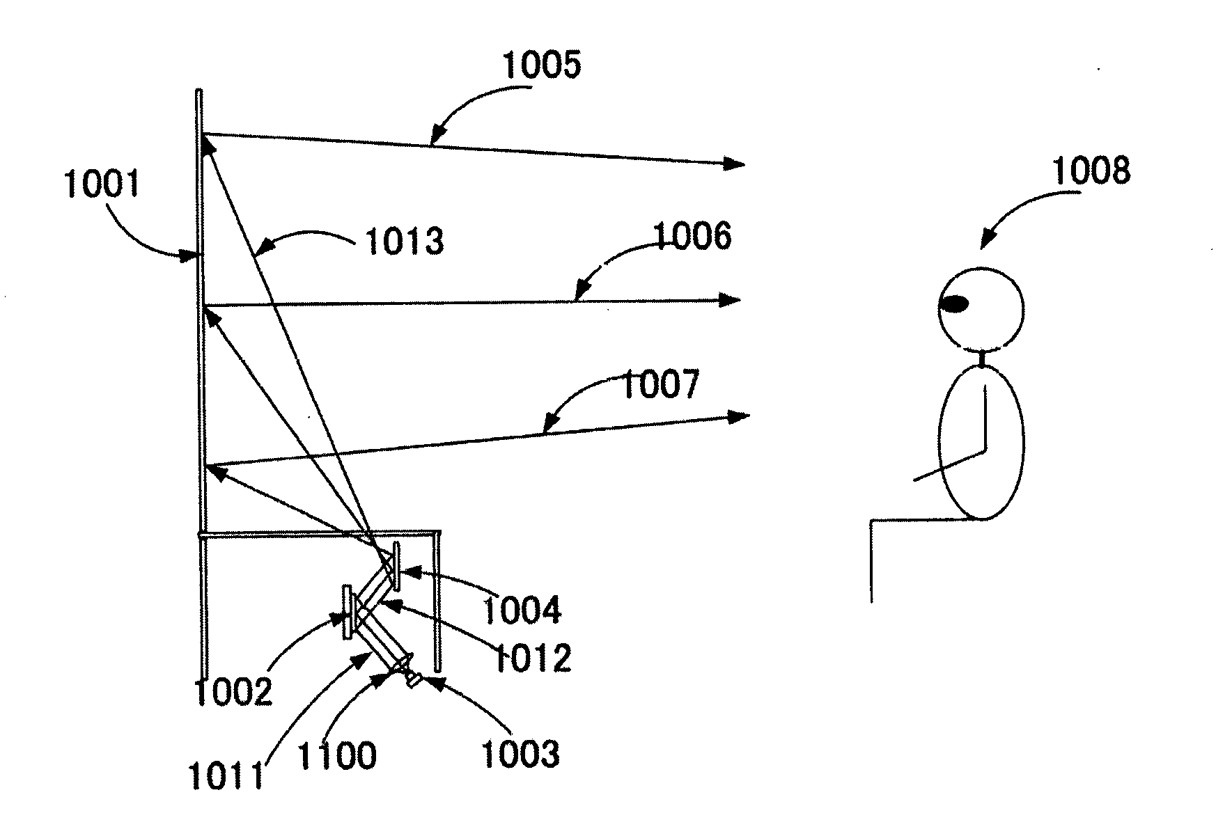
[0076]FIG.-10 illustrates an example of the embodiment of this invention to make a projection optics system, wherein 1) a reflective SLM(1002) is exposed by laser beams(1011) and projected in a tilted direction substantially away from the normal (perpendicular) direction of the SLM surface and 2...


PUM


Abstract

A projection display system is disclosed including a laser light source, projection lens or mirror, and screen. This invention enables a decorative screen which hides a display and matches near-by furniture. This invention also discloses a tiny cost-effective laser light source for projection displays.

Description

CROSS REFERENCE TO RELATED APPLICATIONS[0001]This application is a Non-Provisional application of Provisional Applications (62 / 071,310 on Sep. 20, 2014, 62 / 177,760 on Mar. 23, 2015 and 62 / 231,861 on Jul. 18, 2015) and is a Continuation in Part (CIP) of Patent Application PCT / US 14 / 00135 filed on May 28, 2014 and its Provisional Application 61 / 855,948 on May 28, 2013, which is also a Continuation in Part of patent application Ser. No. 11 / 285,881 filed on Nov. 23, 2005 and issued into U.S. Pat. No. 7,595,828.TECHNICAL FIELD[0002]This invention relates to a display system for projecting an image. More particularly, this invention provides a projection optics enabling a projection display with laser light sources with substantially simpler manufacturing method and lower cost disclosing a light source through projection screen suitable for laser light sources.BACKGROUND ART[0003]Projection display started from a front projector as a movie theatre, wherein a projection display projects im...

Claims


Application Information

Patent Timeline
IPC IPC(8): G03B21/10G02B27/42G03B21/28G03B21/62G02B5/02G02B3/08G03B21/20G02B27/48
CPCG03B21/10G03B21/2013G03B21/2033G02B27/425G02B27/48G03B21/208G02B5/0226G02B5/0289G02B3/08G03B21/28G03B21/62G02B5/32
Inventor ISHII, FUSAO
Owner ISHII FUSAO
Why Eureka
Try Eureka