
Arrangement for and method of imaging targets with improved light collecting efficiency over extended range of working distances

a technology of image capture and light collection efficiency, applied in the field of arrangement for, and a method of, electrooptically reading targets by image capture, can solve the problems of generating dust to obscure the lens, generating objectionable, annoying, and generating a hum

Active Publication Date: 2016-12-08
SYMBOL TECH LLC
View PDF5 Cites 7 Cited by
  • Summary
  • Abstract
  • Description
  • Claims
  • Application Information

AI Technical Summary

Benefits of technology

The present invention relates to an improved imaging lens assembly for an imaging reader that can capture targets over a wide range of working distances and without the need for bright illumination. The lens assembly has a magnified entrance pupil and an improved light collecting efficiency, making it faster and more compact than existing mechanical lens movements. The lens assembly is designed to be used in a handheld or hands-free mode for capturing return light from targets. The technical effects of the invention include improved image quality, reduced vibration, lower power consumption, and improved light collecting efficiency.

Problems solved by technology

However, this mechanical lens movement is disadvantageous for several reasons.
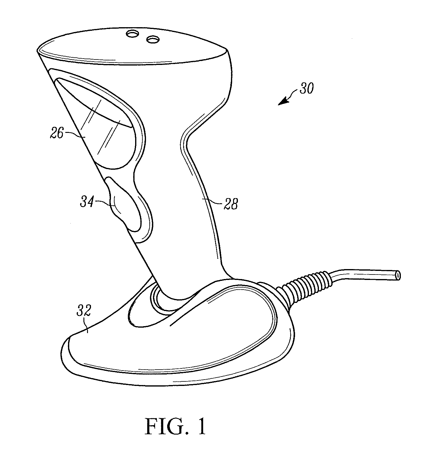
First, the mechanical lens movement generates vibrations which, in the case of a handheld reader, may be propagated through the reader to the user's hand, may generate dust to obscure the lenses, and may generate an objectionable, annoying, audible hum.
In addition, the voice coil motor is very susceptible to hand motion, consumes electrical power, is expensive and notoriously slow, can be unreliable, occupies space, and increases the overall weight, size and complexity of the reader.
Although the liquid lens focuses faster than a lens that is mechanically moved, the liquid lens has a small entrance pupil limited by its available, small active area on the meniscus.
As a result, the liquid lens has a low light collecting efficiency and requires the illuminating light assembly to emit illumination light with a higher intensity or brightness to compensate for the poor light collection, together with a concomitant consumption of extra electrical power.
Bright illumination shining out of the reader can be annoying or uncomfortable to an operator, or to other persons nearby the reader.
Moreover, the liquid lens by itself has a very limited optical power, thereby restricting the working distance range.

Method used


Image

  • Arrangement for and method of imaging targets with improved light collecting efficiency over extended range of working distances
  • Arrangement for and method of imaging targets with improved light collecting efficiency over extended range of working distances
  • Arrangement for and method of imaging targets with improved light collecting efficiency over extended range of working distances

Examples


Embodiment Construction

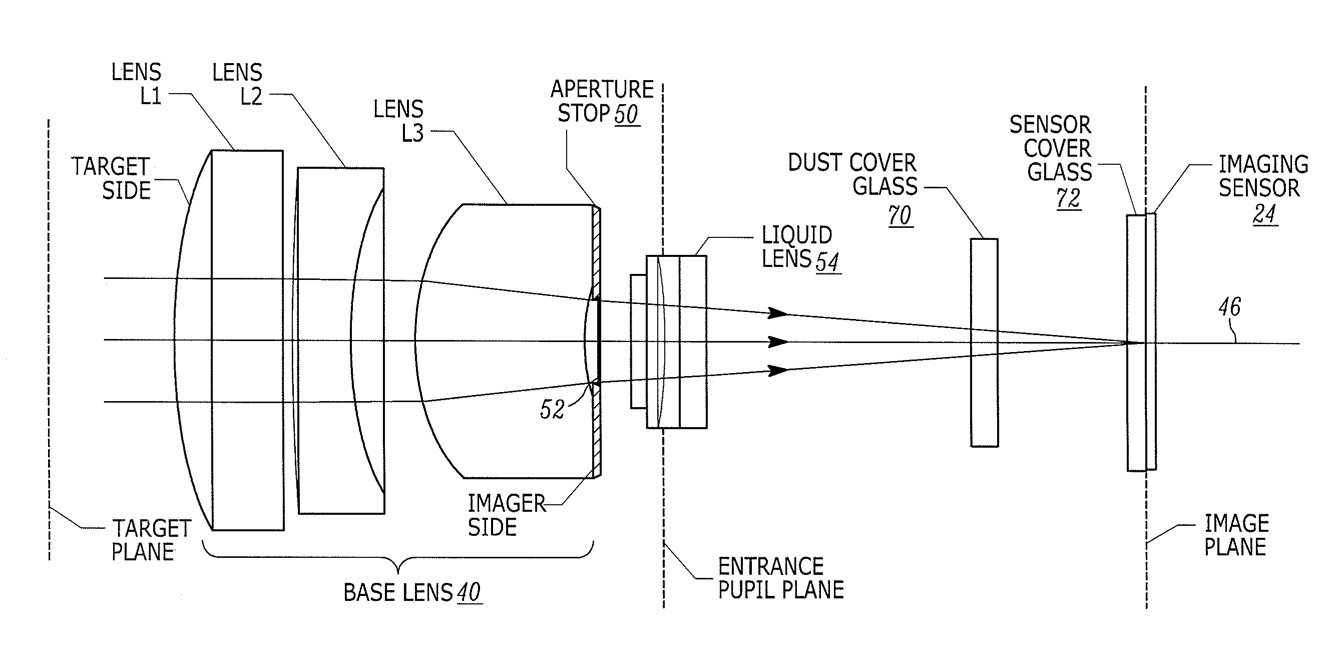
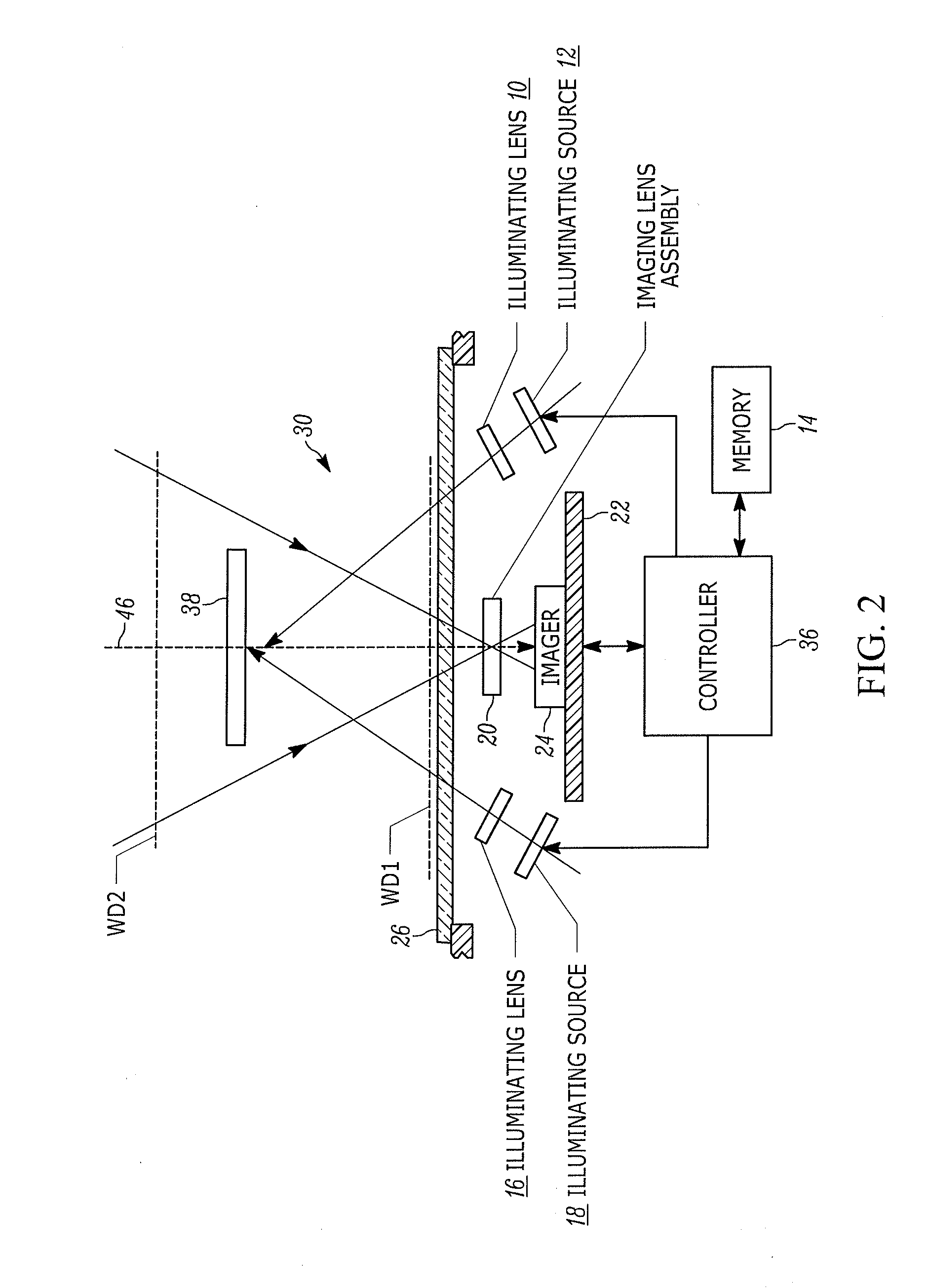
[0015]In accordance with one feature of this disclosure, an imaging lens assembly captures return light from a target, e.g., a bar code symbol, over a field of view of an array of image sensors of a solid-state imager, and projects the captured return light onto the array during electro-optical reading of the target. The imaging lens assembly includes a base lens through which the captured return light passes along an optical axis. The base lens is preferably configured of a plurality or group of lenses arranged along the optical axis. The base lens has an optical power, a target side facing the target, and an imager side facing the imager. The imaging lens assembly also includes an aperture stop in direct surface area contact with the imager side of the base lens. The aperture stop has an aperture through which the optical axis extends and the captured return light passes. The aperture is magnified in apparent size by the optical power of the base lens to form a magnified entrance ...


PUM


Abstract

An imaging lens assembly for an imaging reader includes a base lens having an optical power, a target side facing a target, and an imager side facing an imager. An aperture stop directly contacts the imager side and has an aperture through which return light from the target passes. The aperture is magnified in apparent size by the optical power of the base lens to form a magnified entrance pupil as seen through the target side. A variable focus liquid lens focuses the return light captured by the magnified entrance pupil over an extended range of working distances onto the imager. The magnified entrance pupil captures more of the return light from the target to pass through the base lens and the liquid lens to the imager, and also allows the target to be illuminated with a lower brightness to conserve electrical power.

Description

BACKGROUND OF THE INVENTION[0001]The present disclosure relates generally to an arrangement for, and a method of, electro-optically reading targets by image capture and, more particularly, to an imaging lens assembly having a magnified entrance pupil for capturing return light from a target with an improved light collecting efficiency over an extended range of working distances in a field of view of a solid-state imager of an imaging reader, and for projecting the captured return light onto the imager during reading of the target.[0002]Solid-state imaging systems or imaging readers have been used in many industries, such as retail, manufacturing, warehousing, distribution, postal, transportation, logistics, etc., to image various symbol targets, such as one- and two-dimensional bar code symbols to be electro-optically decoded and read by image capture. A known imaging reader includes a solid-state imager, e.g., a one- or two-dimensional charge coupled device (CCD) or a complementary...

Claims


Application Information

Patent Timeline
IPC IPC(8): G06K7/10G02B3/14
CPCG06K7/10811G02B3/14G06K7/10732G02B9/34G02B26/005G06K7/10722G06K7/10831G02F1/294G06K7/10881
Inventor CHEN, CAIHUATAN, CHINH
Owner SYMBOL TECH LLC
Learn More