Video doorbell system and related power supply adjusting method

a doorbell and video technology, applied in the field of video doorbell systems, to achieve the effect of avoiding circuit damag

Active Publication Date: 2016-12-08
VIVOTEK INC
View PDF2 Cites 2 Cited by
  • Summary
  • Abstract
  • Description
  • Claims
  • Application Information

AI Technical Summary

Benefits of technology

[0008]The video doorbell system of the present invention has the mode switching controller providing the remote controlling function. The video generating module of the first embodiment can be preferably applied to the mechanical doorbell, and the video generating module of the second embodiment can be preferably applied to the electric doorbell. The external power source is connected with the video generating module while the mode switching controller is in the standby mode, and is transformed to connect with the ringtone generating unit while the doorbell is actuated, so that the video generating module can adequately use energy of the external power source without constraint of the doorbell and the related ringtone generating unit. Besides, the video generating module can include a plurality of diodes and capacitors selectively, the diodes can avoid circuit damage by signal backflow, and the capacitors provide auxiliary filtering function accordingly. Comparing to the prior art, the video doorbell system of the present invention can provide sufficient energy to the video generating module for execution of the image capturing function by keeping original function of the common doorbell.

Problems solved by technology

However, alternative of the doorbell 54 and the camera 56 does not conform to consumer's demand, and design of a doorbell system capable of keeping function of the doorbell and the camera is an important issue in the related industry.

Method used


Image

  • Video doorbell system and related power supply adjusting method
  • Video doorbell system and related power supply adjusting method
  • Video doorbell system and related power supply adjusting method

Examples


first embodiment

[0021]Please refer to FIG. 3 and FIG. 4. FIG. 4 is a diagram of the video generating module 16A according to the present invention. The video generating module 16A can include an image capturing unit 24, a first circuit switch 26 and a second circuit switch 28. The first circuit switch 26 and the second circuit switch 28 are connected to the image capturing unit 24 respectively in series connection and parallel connection. While the mode switching controller 18 is switched into the first mode, the first circuit switch 26 is short-circuited to connect the external power source 14 with the power storing component 20 and the image capturing unit 24, and the second circuit switch 28 is open-circuited. As the pressing unit is actuated, the first circuit switch 26 is switched to an open-circuited mode and the second circuit switch 28 is switched to a close-circuited mode, the mode switching controller 18 is driven by the control signal of the second circuit switch 28 to switch into the se...

second embodiment

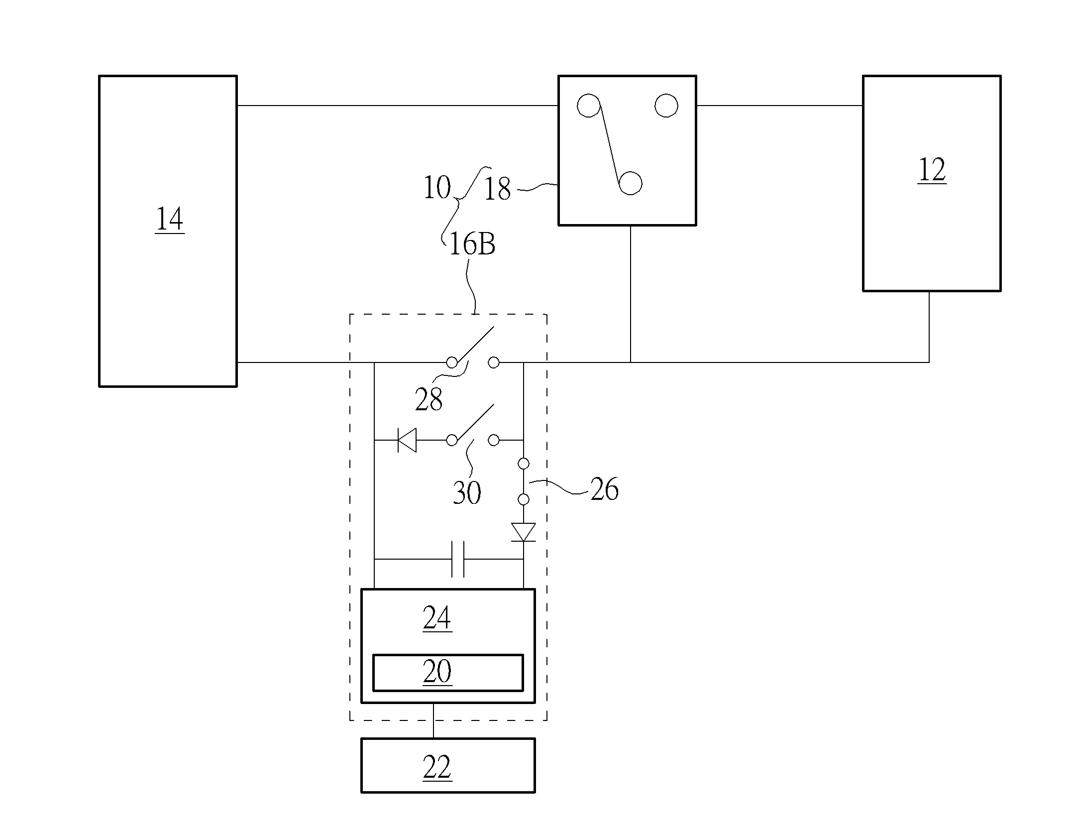
[0023]Please refer to FIG. 3 and FIG. 5. FIG. 5 is a diagram of the video generating module 16B according to the present invention. The video generating module 16B can include the image capturing unit 24, the first circuit switch 26, the second circuit switch 28 and a third circuit switch 30. The first circuit switch 26 is electrically connected to the image capturing unit 24 in series connection, and the second circuit switch 28 and the third circuit switch 30 are electrically connected to the image capturing unit 24 in parallel connection. While the mode switching controller is into the first mode, the first circuit switch 26 is short-circuited to connect the external power source 14 with the power storing component 20 and the image capturing unit 24, and the second circuit switch 28 and the third circuit switch 30 are open-circuited. As the pressing unit 22 is actuated, the first circuit switch 26 is switched to the open-circuited mode and the second circuit switch 28 is switched...


PUM


Abstract

A video doorbell system coupled with a ringtone generating unit is applied by a power supply adjusting method and includes a video generating module and a mode switching controller. The video generating module includes a power storing component. The mode switching controller can be switched into a first mode or a second mode in a remote controlling manner. While the mode switching controller is switched into the first mode, the ringtone generating unit is bypassed and an external power source is connected to the video generating module, so as to charge the power storing component by the external power source. While the mode switching controller is switched into the second mode, the video generating module is bypassed and the external power source is connected to the ringtone generating unit, and the video generating module can execute image capturing function via the power storing component.

Description

BACKGROUND OF THE INVENTION[0001]1. Field of the Invention[0002]The present invention relates to a video doorbell system, and more particularly, to a video doorbell system and a related power supply adjusting method capable of matching any doorbell without constraint.[0003]2. Description of the Prior Art[0004]Please refer to FIG. 1. FIG. 1 is a diagram of a doorbell circuit system in the prior art. The conventional doorbell circuit system 50 includes a power supply 52, a doorbell 54 and a camera 56. The doorbell 54 and the camera 56 are electrically connected to the power supply 52 in series connection for establishing the circuit system. Energy acquirement of the camera 56 is affected by electric consumption of the doorbell 54; for providing sufficient energy to the camera, the doorbell 54 is short-circuited and the camera 56 can acquire full energy of the power supply 52 for complete operation. However, alternative of the doorbell 54 and the camera 56 does not conform to consumer'...

Claims


Application Information

Patent Timeline
Patent Type & Authority Applications(United States)
IPC IPC(8): H04N5/232G08B3/10H04N7/18
CPCH04N5/23241G08B3/10H04N7/186G07C9/00944H02J9/061H04N23/651
Inventor HUANG, YEN-CHIEH
Owner VIVOTEK INC
Why Eureka
Try Eureka