Systems and methods for breadboard sytle printed circuit board

a technology of printed circuit board and breadboard, which is applied in the direction of circuit masks, printed element electric connection formation, inspection/indentification of circuits, etc., can solve the problems of laborious process, tedious and time-consuming use of breadboard, and significant amount of time in the process of connecting

Active Publication Date: 2016-12-08
KHO SAMUEL P
View PDF8 Cites 7 Cited by
  • Summary
  • Abstract
  • Description
  • Claims
  • Application Information

AI Technical Summary

Problems solved by technology

However, using a breadboard can be tedious and time consuming.
Even in a simple circuit that process is cumbersome, but in a complex circuit, that process takes a significant amount of time to form the connections between the parts of the breadboard that already have internal connections.
However, the hookup wires still need to be cut, striped and soldered to the PCB, which is a laborious process.
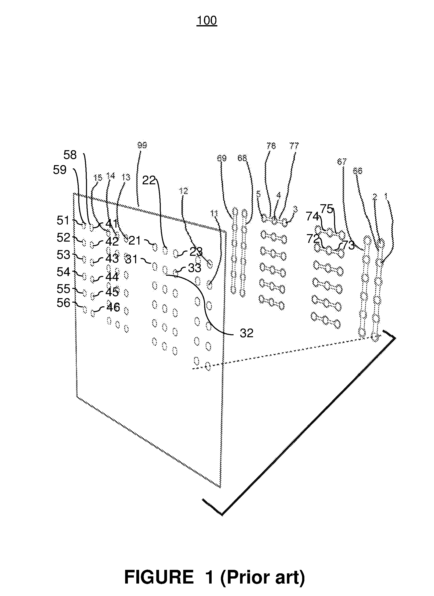
However, with the prior art PCB, hookup wires must be used to form connections between power rails and between PTHs that are not electrically connected.

Method used


Image

  • Systems and methods for breadboard sytle printed circuit board
  • Systems and methods for breadboard sytle printed circuit board
  • Systems and methods for breadboard sytle printed circuit board

Examples


Embodiment Construction

[0040]In the following description, for purposes of explanation, specific details are set forth in order to provide an understanding of the invention. It will be apparent, however, to one skilled in the art that the invention can be practiced without these details. Furthermore, one skilled in the art will recognize that embodiments of the present invention, described below, may be implemented in a variety of ways, such as a process, an apparatus, a system, a device, or a method on a tangible computer-readable medium.

[0041]Components, or modules, shown in diagrams are illustrative of exemplary embodiments of the invention and are meant to avoid obscuring the invention. It shall also be understood that throughout this discussion that components may be described as separate functional units, which may comprise sub-units, but those skilled in the art will recognize that various components, or portions thereof, may be divided into separate components or may be integrated together, includ...


PUM


Abstract

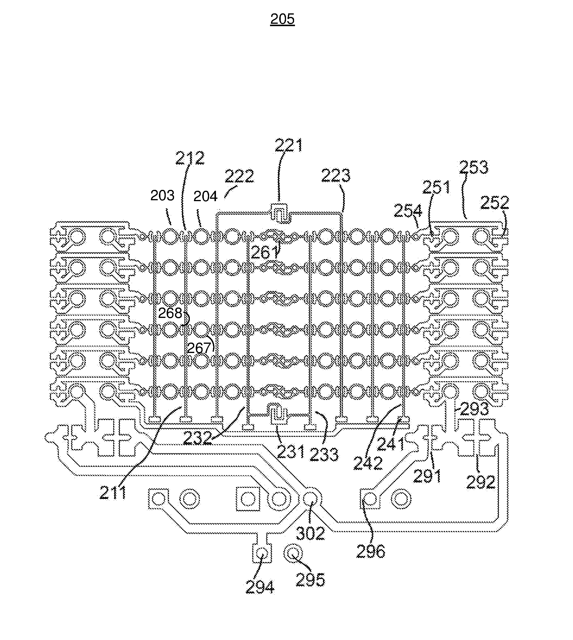
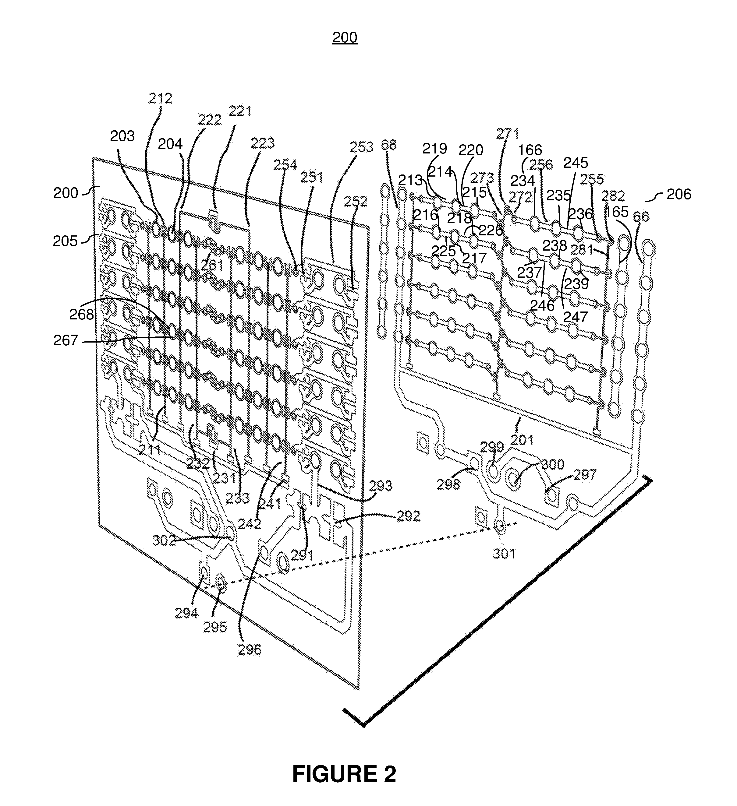
The present invention relates generally to electric circuit testing, building, or implementing using a breadboard style PCB. Aspects of the present invention include eliminating the need to use hookup wires when building and testing electric circuits on PCBs. In embodiments, a PCB system having rows and columns of signal tie points connected in a breadboard layout and using an embedded wire and a solder bridge to form partial connections between signal tie points. In embodiments, the embedded wire and solder bridge is capable of connecting a column of signal tie points. In embodiments, the embedded wire and solder bridge is capable of connecting a power rail to a signal tie point. Thus, a circuit can be implemented and tested by applying a small amount of solder to the solder bridge without the need for hookup wires.

Description

CROSS-REFERENCE TO RELATED APPLICATION[0001]This patent application claims priority to co-pending and commonly-owned U.S. Pat. App. No. 62 / 171,554, filed on Jun. 5, 2015, entitled “Breadboard-style Printed Circuit Board with reduced or eliminated need of Hookup Wires,” and listing Samuel P. Kho as inventor, which patent document is incorporated by reference herein in its entirety and for all purposes.BACKGROUND[0002]Field of Invention[0003]The present invention relates generally to printed circuit boards and more particularly to protoboards with a bread board style layout.[0004]Description of the Related Art[0005]Often when designing a circuit or creating a circuit engineers and home hobbyists use a breadboard to test the circuit. A breadboard is a board made of plastic with plastic holes to insert electronic components and wires. A breadboard consists of a perforated block of plastic with numerous tin plated phosphor bronze or nickel silver alloy spring clips under the perforations...

Claims


Application Information

Patent Timeline
Patent Type & Authority Applications(United States)
IPC IPC(8): H05K1/02H05K1/09H05K3/00H05K1/11H05K3/40
CPCH05K1/0286H05K1/11H05K3/40H05K2201/09209H05K3/0073H05K1/09H05K3/4007H05K1/0215H05K1/0269H05K1/0289H05K3/1216H05K2201/0305H05K2201/09254H05K2201/09563H05K2201/09572H05K2201/09609H05K2203/166H05K1/029H05K1/0292H05K1/0293
Inventor KHO, SAMUEL P.
Owner KHO SAMUEL P
Why Eureka
Try Eureka