
Locating light sources using aircraft

a technology for locating light sources and aircraft, applied in the field of locating light sources using aircraft, can solve the problems of affecting air traffic, based detection or deployment of special purpose aircraft, and being unable to effectively detect the majority of attackers on aircraft with light sources

Active Publication Date: 2016-12-15
THE BOEING CO
View PDF20 Cites 8 Cited by
  • Summary
  • Abstract
  • Description
  • Claims
  • Application Information

AI Technical Summary

Benefits of technology

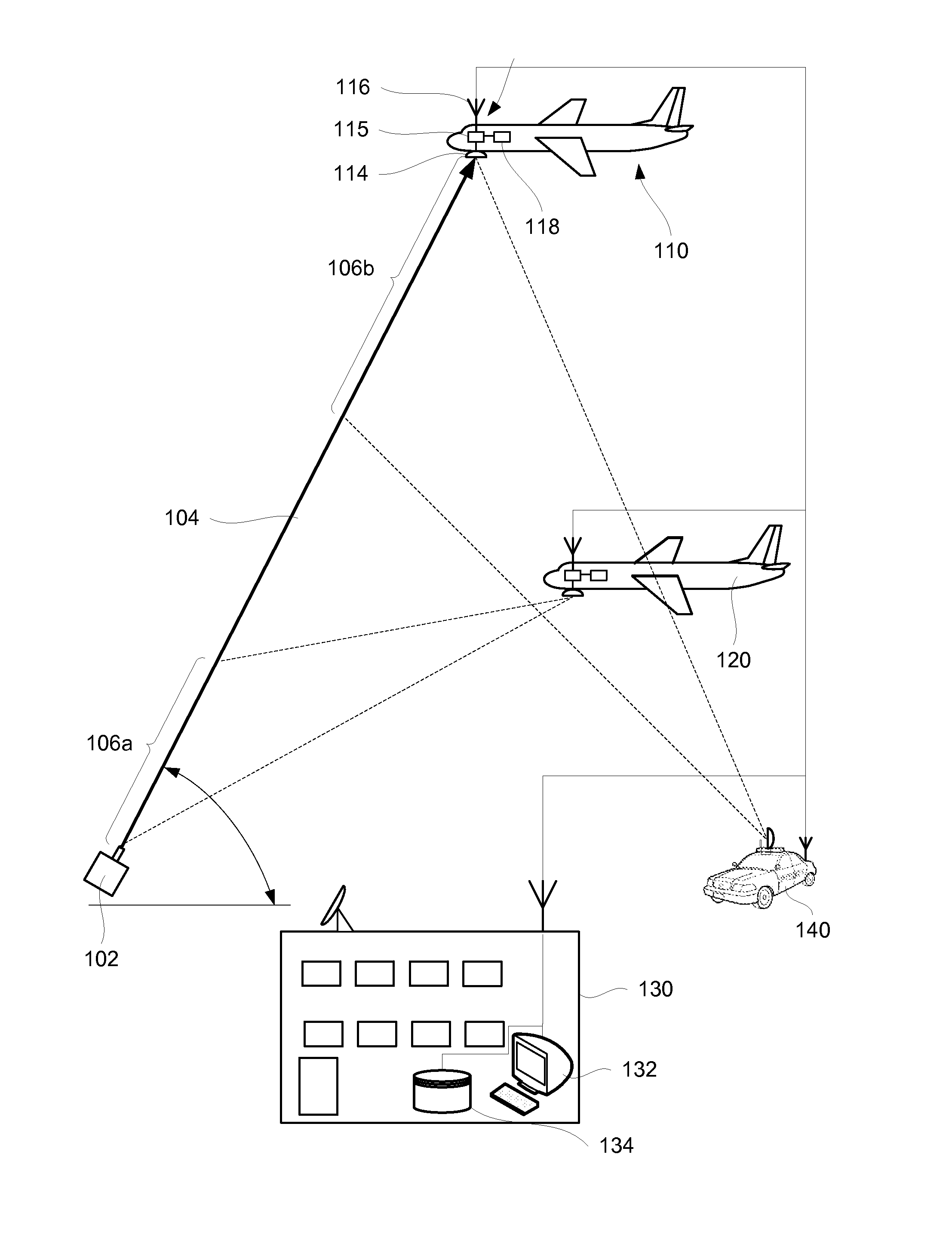
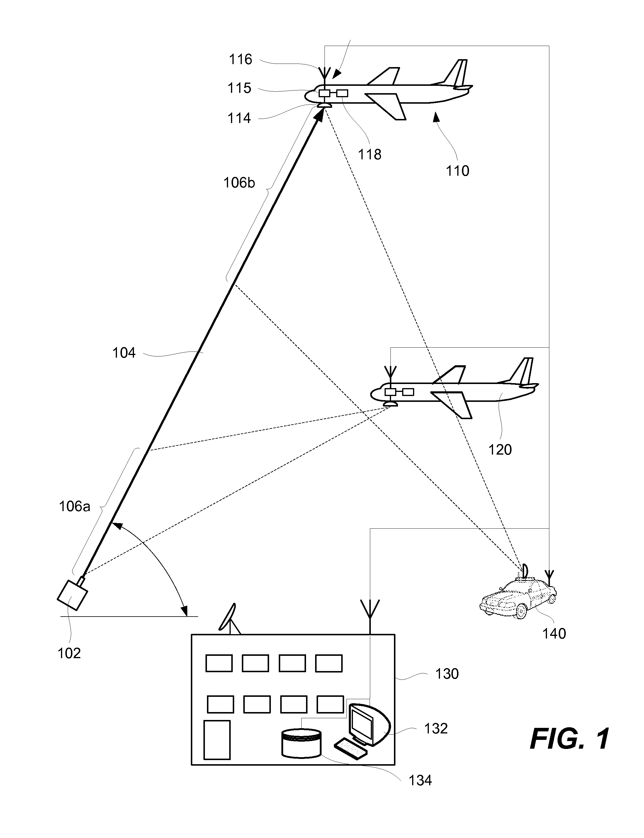
The patent describes a method and system for identifying the location of light sources from airborne aircraft. The light sources are ground based and can be low power lasers or other devices. The method involves detecting the output of the light source and analyzing it to determine its relative position to the aircraft. This information can be used to estimate the location of the light source. The method can be performed using a detecting module on the aircraft or a user on the ground. The analysis of the data sets can be performed at a ground based node or at another ground based node. The system can also involve transmitting the data sets to a different aircraft or to a ground based node for analysis. The technical effect of the patent is to provide a more accurate and efficient way to identify the location of light sources from airborne aircraft.

Problems solved by technology

The existing solutions, such as ground based detection or deployment of special purpose aircraft, are generally not capable of effectively detecting most attackers on aircraft with light sources.
The special purpose aircraft are costly to operate and may interfere with air traffic.
As noted above, attacks using light sources are often performed in areas with heavy air traffic and deploying additional aircraft in these areas may be dangerous.
Furthermore, a special purpose aircraft may not be able to cover all areas of possible attacks, which may be any area with low altitude air traffic.
The laser output may be generated maliciously, e.g., to attack an aircraft, or may be unintentionally directed to the aircraft and interfere with operation of the aircraft.

Method used


Image

  • Locating light sources using aircraft
  • Locating light sources using aircraft
  • Locating light sources using aircraft

Examples


Embodiment Construction

[0025]In the following description, numerous specific details are set forth in order to provide a thorough understanding of the presented concepts. The presented concepts may be practiced without some or all of these specific details. In other instances, well known process operations have not been described in detail so as to not unnecessarily obscure the described concepts. While some concepts will be described in conjunction with the specific examples, it will be understood that these examples are not intended to be limiting.

[0026]Reference herein to “one example” or “one aspect” means that one or more feature, structure, or characteristic described in connection with the example or aspect is included in at least one implementation. The phrase “one example” or “one aspect” in various places in the specification may or may not be referring to the same example or aspect.

INTRODUCTION

[0027]Methods and systems described herein are used for identifying location of light sources, such as...


PUM


Abstract

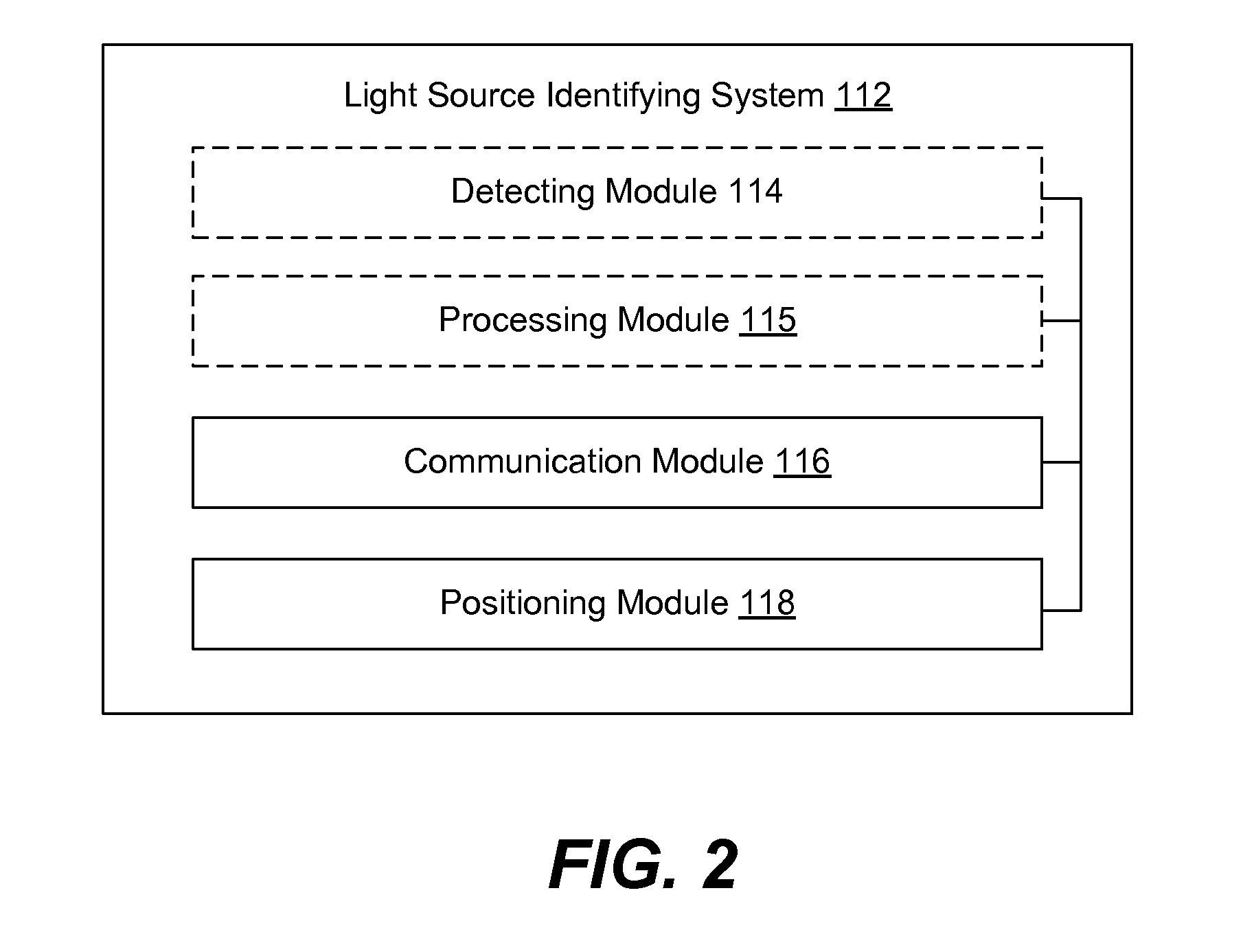
Provided are methods and systems for identifying location of light sources from airborne aircraft. Light sources are ground based and may be low power lasers and other like devices. An aircraft equipped with a detecting module, such as a camera of a ground maneuver camera system, may defect light source output and associate this output with the relative position of the aircraft to the light source. This information may be analyzed together with aircraft location information (at the time of light source detection) to generate a light source location estimate. In some embodiments, other information, such as transmission from other aircraft and / or ground based nodes can be used. The estimate may be transmitted to a ground based node, such as a law enforcement unit. The data from multiple aircraft and / or ground based nodes may be aggregated to more precisely identify the light source location.

Description

BACKGROUND[0001]Widespread availability of low-power light sources (e.g., laser pointers) and other sources of concentrated light led to many recent attacks on aircraft, particularly near airports and high air traffic areas. These attacks may cause harm to pilots and, in some cases to, aircraft. For example, a high intensity light directed at a pilot cabin may blind pilots and effectively disable them during critical portions of the flight, such as during takeoff and / or landing. Most attacks happen when aircraft are at low altitudes. Light sources are typically positioned on the ground. While existing legal mechanisms are designed to heavily penalize laser attackers and other similar attackers, these mechanisms have not been effective in discouraging these individuals, and unfortunately the frequency and severity of attacks continue to rise. One problem is difficulty in locating attackers on the ground. Attacks can be performed from large areas surrounding airports. Often, these are...

Claims


Application Information

Patent Timeline
IPC IPC(8): G06T7/00G06K9/00
CPCG06T7/0042G06K9/0063H04B7/18506H04L67/12H04B7/18523G06T2207/10032G06T7/73Y02D30/70G01S5/0009G01S17/06G01S5/0027G01S3/78G06T7/70G01S5/0018G01S5/16
Inventor SAMPIGETHAYA, RADHAKRISHNA G.
Owner THE BOEING CO
Learn More