

Light spot indication robot and light spot indication method thereof
- Summary
- Abstract
- Description
- Claims
- Application Information
AI Technical Summary
Benefits of technology
Problems solved by technology
Method used
Image

Examples
first embodiment
The First Embodiment
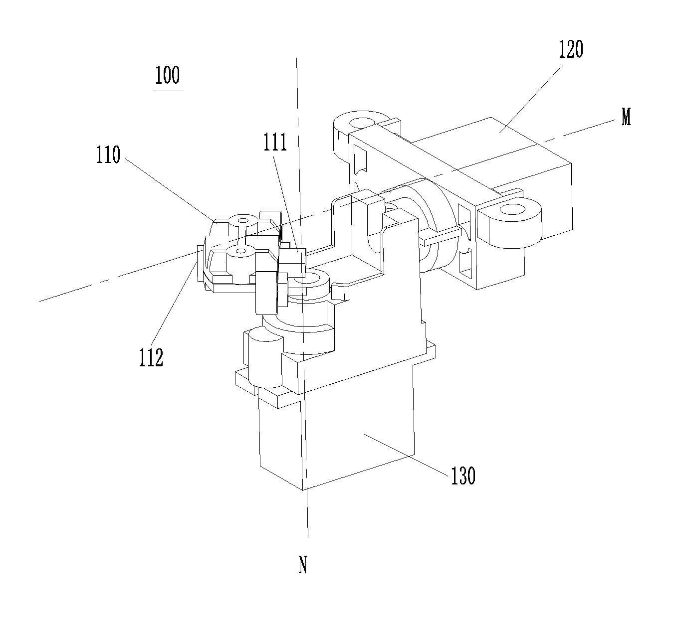
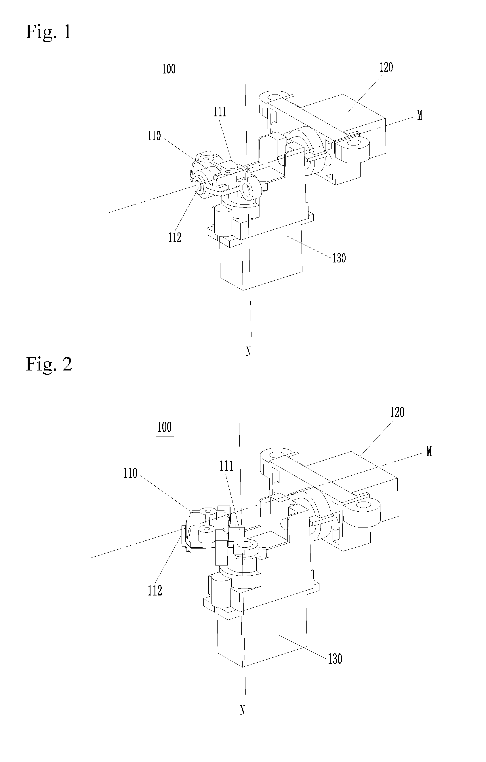
[0035]The present invention provides a light spot indication robot comprising a robot body which is arranged with a control module, an imaging module and a laser indication module, wherein the laser indication module emits a laser beam, the imaging module shoots to-be-indicated objects to form an image plane, and the laser beam and the to-be-indicated objects are projected onto the image plane to form a laser spot projection position and to-be-indicated object projection positions, respectively. The light spot indication robot is further arranged with a signal input module. According to content shown on the image plane of the to-be-indicated objects shot by the imaging module, the target object among the to-be-indicated objects is determined by input information of the signal input module. The control module controls the laser indication module to move, so that the laser spot projection position coincides with a projection position of the target object in the ima...
second embodiment
The Second Embodiment
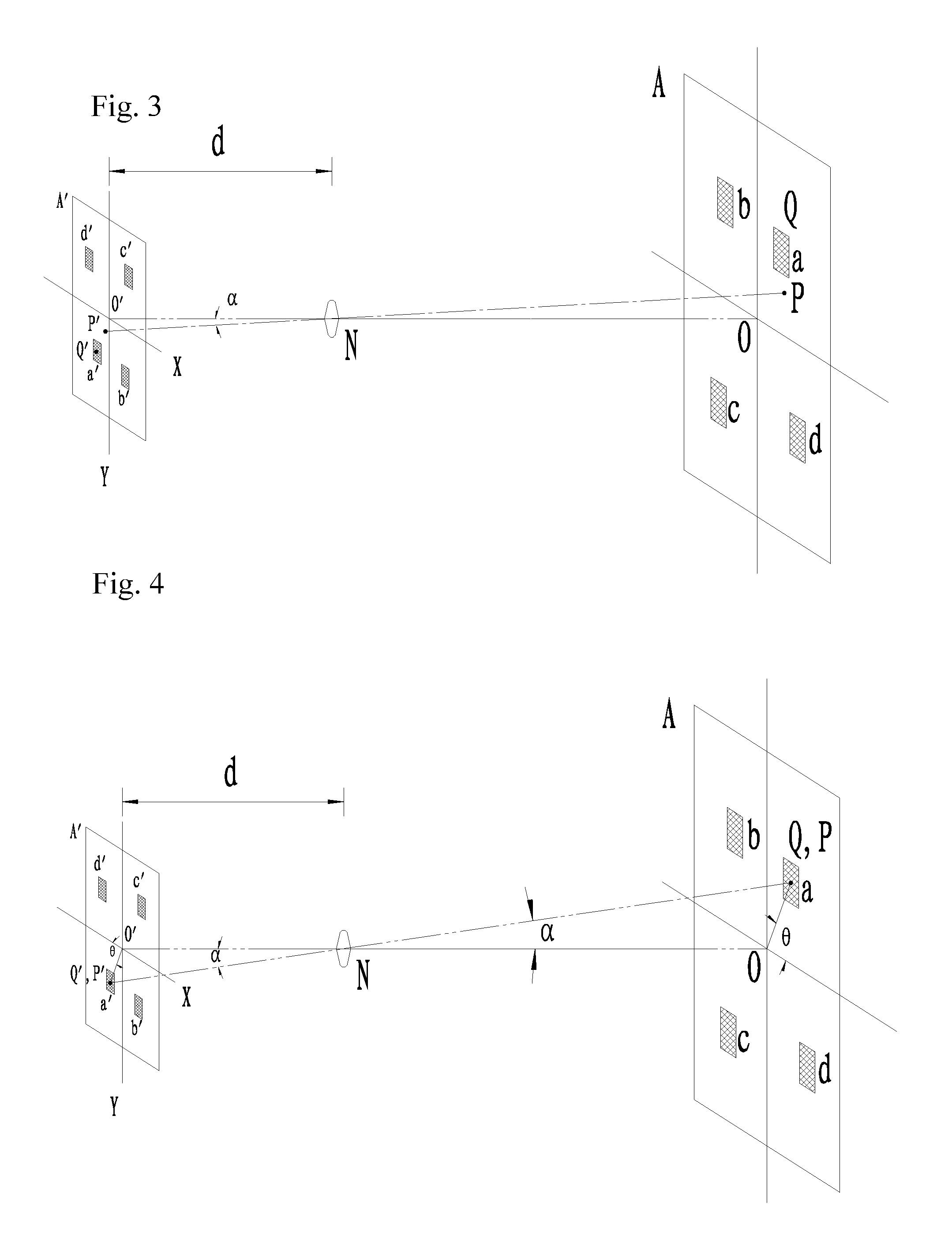
[0045]In order to cause the real-time laser spot projection position P′ to coincide with the projection position Q′ of the product that is required to be purchased in the image plane A′, this embodiment further provides the operation manner other than the above operation manner in which the angle θ between line O′Q′ and the X axis is calculated and then the free end of the laser pointer is driven to swing.
[0046]As shown in FIG. 3 in combination with FIG. 4, specifically, in this embodiment, when the centerline of the laser pointer is on the same line with the output shaft of the first motor, the laser spot projection position in the image plane is set as O′, and the distance between the focal point N of the camera lens in the imaging module and the image plane A′ is d; and when the output shaft of the second motor is parallel to the X axis, an angle between the second motor and the X axis is defined as 0°.
[0047]The Step 3 specifically comprises:
[0048]Step 3-1′: ...
third embodiment
The Third Embodiment
[0052]Further, except for the structure described in the first embodiment and the second embodiment, the structure configuration of the driving means in the laser indication module may comprise a third motor and a forth motor, wherein the third motor and the forth motor drive the laser pointer to swing in X axis direction and Y axis direction that is vertical to the X axis direction, respectively. The indication method performed by the robot adopting such driving means is different from that of the above two embodiments, in which the first two Steps 1 and 2 are the same as those of the first embodiment and the second embodiment, but the Step 3 is partially different. Specifically, the imaging module shoots and obtains the real-time laser spot projection position P′ in the image plane, and the projection position P′ is compared with the projection position Q′ of the target object. The Step 3 specifically comprises: causing the laser pointer to swing in the X axis ...
PUM
 Abstract
Description
Claims
Application Information