
Pallet transporting device

a technology of transporting device and pallet, which is applied in the field of pallet trucks, can solve the problems of cost, ownership and maintenance cos

Inactive Publication Date: 2016-12-22
OCONNELL BRIAN
View PDF5 Cites 17 Cited by
  • Summary
  • Abstract
  • Description
  • Claims
  • Application Information

AI Technical Summary

Benefits of technology

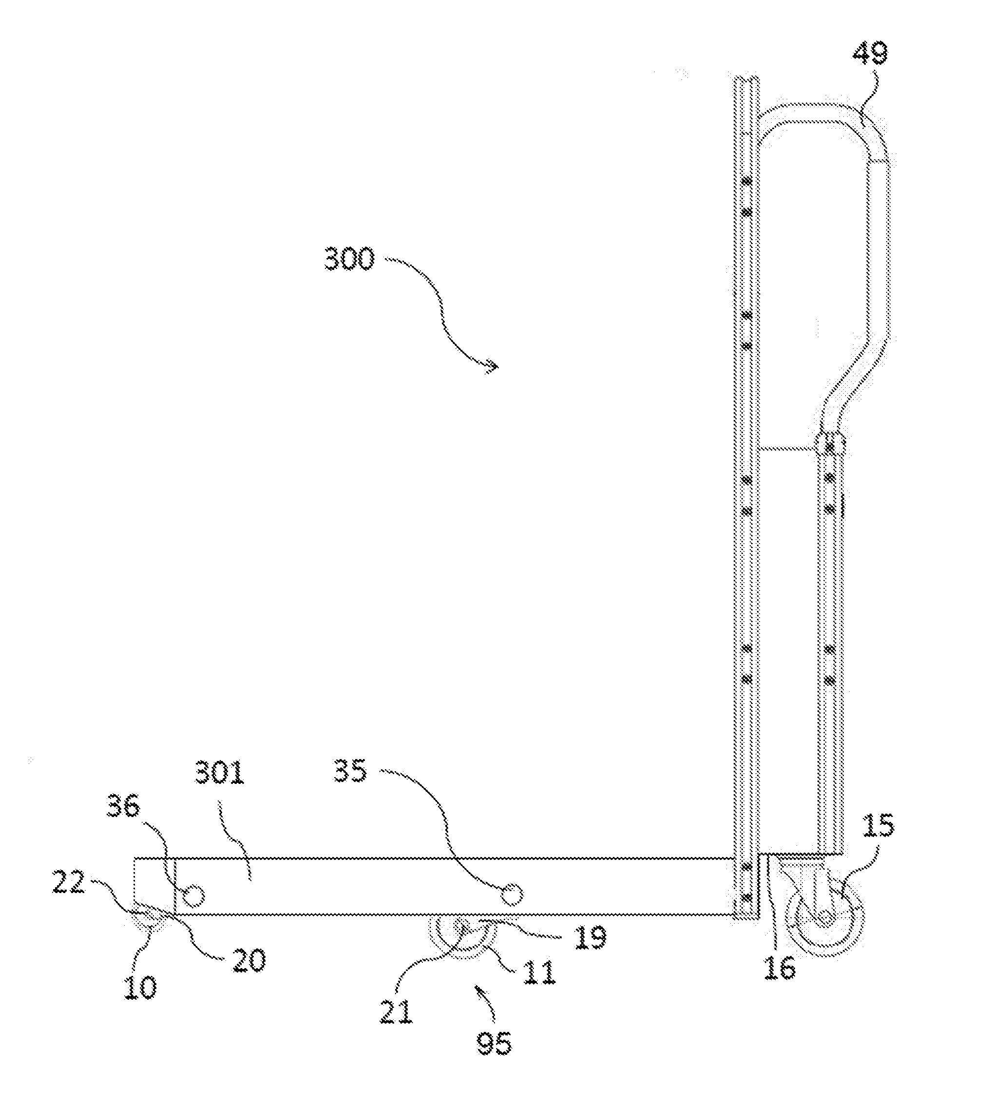
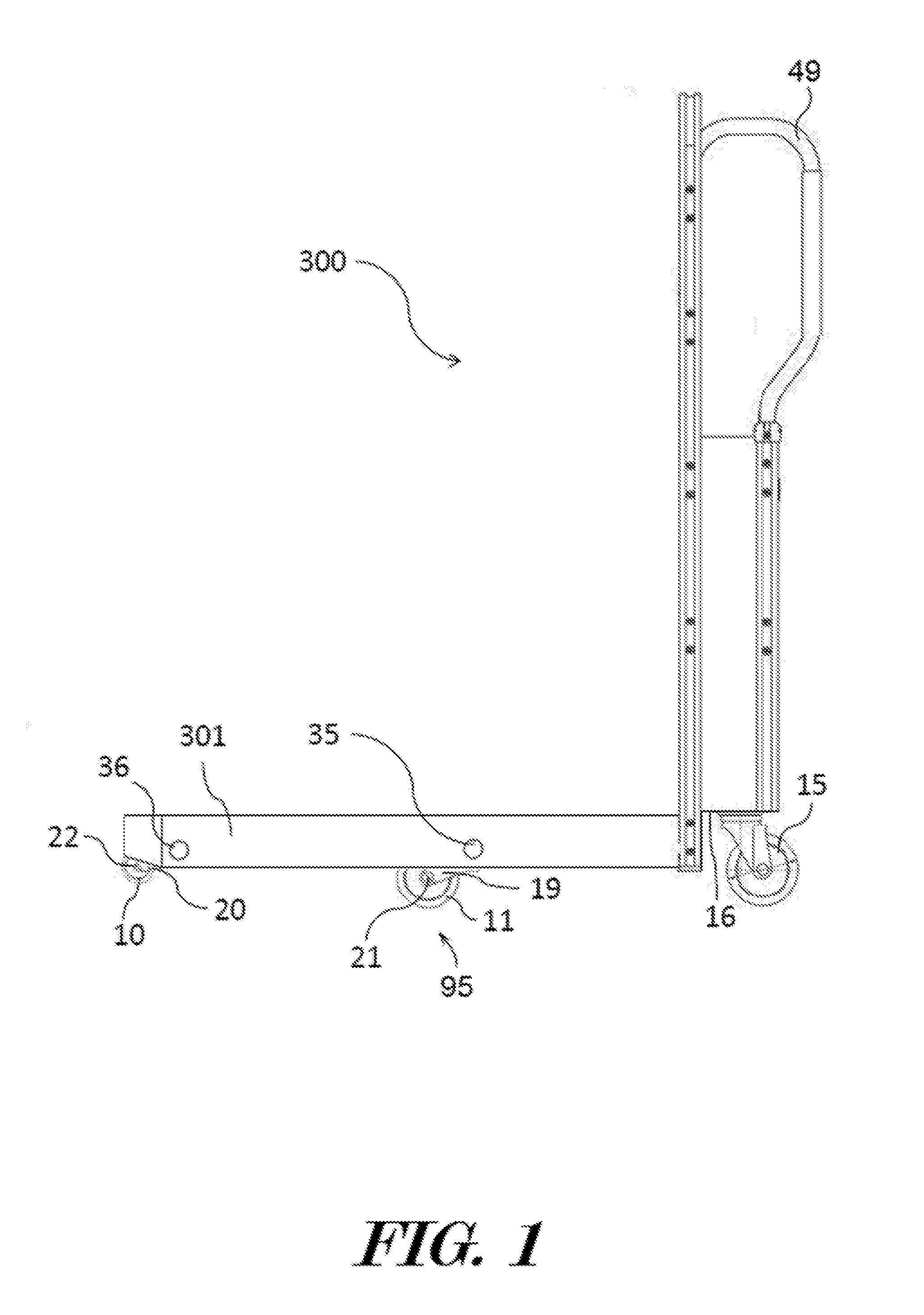
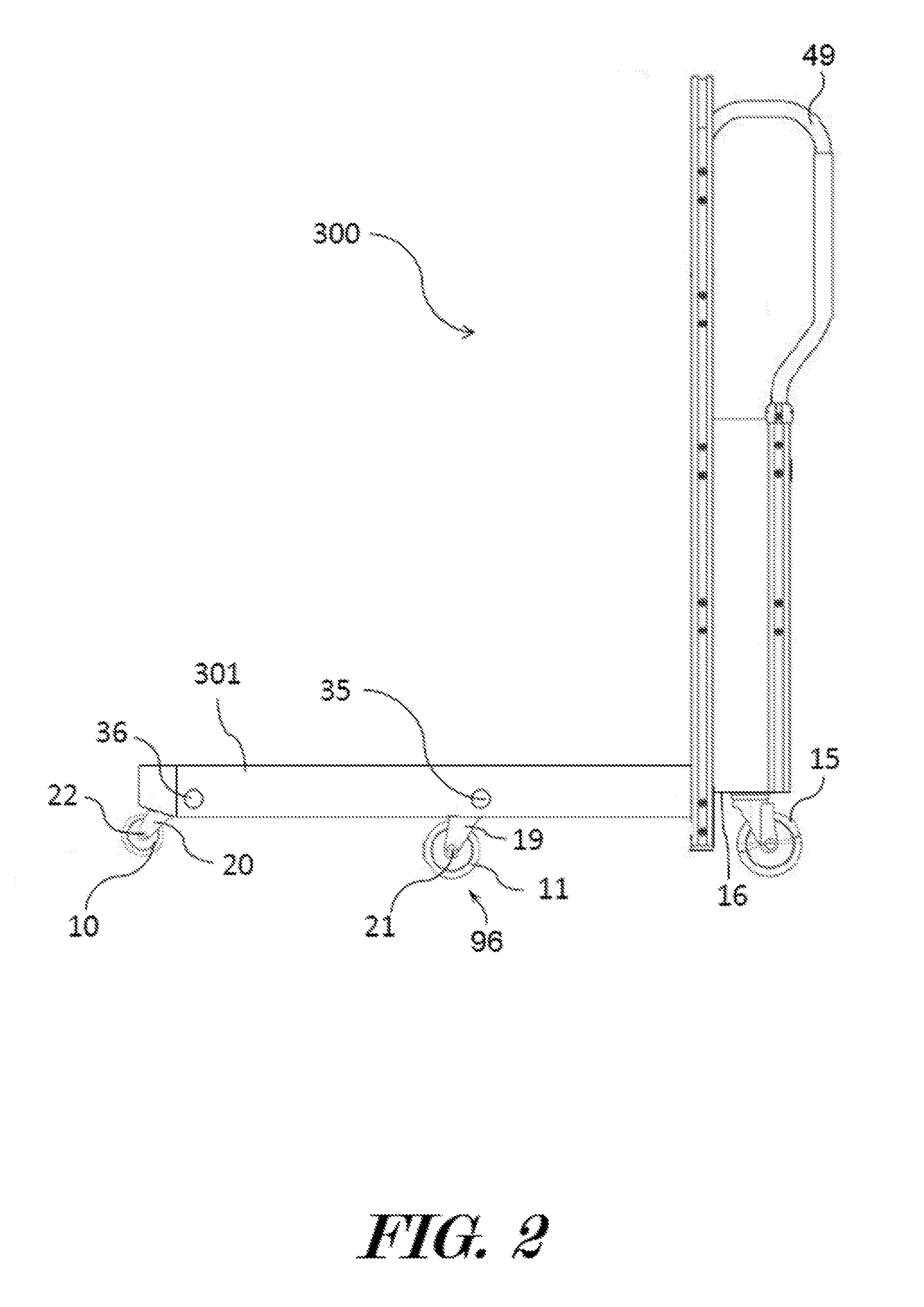
The patent is for a narrow pallet transporting device that can lift, lower, move, or motivate pallets. It includes a rocker arm, a chassis, and two tines (one proximal and one distal) that can hold and move loads. The device also has two horizontal retractable wheels that can move between inner and extended positions. The tines can move synchronously with the rocker arm into the raised or lowered positions. The technical effect of this device is that it allows for efficient and secure movement of high-profile design pallets.

Problems solved by technology

These high profile pallets may have support decks which are 6 inches or higher above the ground to be transported by custom designed lifts which are costly to own and maintain.

Method used


Image

  • Pallet transporting device
  • Pallet transporting device
  • Pallet transporting device

Examples


Embodiment Construction

[0081]The terminology used herein is for the purpose of describing particular embodiments only and is not intended to be limiting of the invention. As used herein, the term “and / or” includes any and all combinations of one or more of the associated listed items. As used herein, the singular forms “a,”“an,” and “the” are intended to include the plural forms as well as the singular forms, unless the context clearly indicates otherwise. It will be further understood that the terms “comprises” and / or “comprising,” when used in this specification, specify the presence of stated features, steps, operations, elements, and / or components, but do not preclude the presence or addition of one or more other features, steps, operations, elements, components, and / or groups thereof.

[0082]Unless otherwise defined, all terms (including technical and scientific terms) used herein have the same meaning as commonly understood by one having ordinary skill in the art to which this invention belongs. It wi...


PUM


Abstract

In some embodiments, the device may comprise a rocker arm, fist tine, and second tine which may be coupled to a chassis. A first proximal wheel yoke having a first retractable load bearing wheel may be pivotally coupled to the first tine. A first distal wheel yoke having a first retractable counter balance wheel may also be pivotally coupled to the first tine. A first tappet may be coupled to the first proximal wheel yoke, to the first distal wheel yoke, and to the rocker arm. A second proximal wheel yoke having a second retractable load bearing wheel may be pivotally coupled to the second tine. A second distal wheel yoke having a second retractable counter balance wheel may also be pivotally coupled to the second tine. A second tappet may be coupled to the second proximal wheel yoke, to the second distal wheel yoke, and to the rocker arm.

Description

CROSS REFERENCE TO RELATED APPLICATIONS[0001]This application is a continuation-in-part of U.S. Non-Provisional application Ser. No. 14 / 843,701, filed on Sep. 2, 2015, entitled “PALLET LIFT”, which claims the benefit of U.S. Provisional Patent Application Ser. No. 62 / 044,643, filed on Sep. 2, 2014, entitled “IMPROVED PALLET LIFT”, the entire disclosures of which are incorporated by reference herein.FIELD OF THE INVENTION[0002]This patent specification relates to the field of pallet trucks. More specifically, this patent specification relates to pallet trucks configured to manipulate a plurality of pallet types including high profile pallets.BACKGROUND[0003]Pallets are commonly used to secure durable goods during transport between various locations. Typically, a pallet comprises a square or rectangular load bearing surface or deck configured to receive goods for storage and transport. Sidewalls with ground contacting legs extend vertically below the deck forming a space or cavity sui...

Claims


Application Information

Patent Timeline
IPC IPC(8): B66F9/065B62B3/06
CPCB62B3/0618B66F9/065B62B2301/02B62B2301/10B62B3/008B62B2205/14B66F9/07504
Inventor O'CONNELL, BRIAN
Owner OCONNELL BRIAN
Learn More