Heating and cooling system for hazardous environments

a technology for hazardous environments and heating and cooling systems, applied in the field of electrically-mechanical devices, can solve the problems of dangerous and immobile current approaches to heating and cooling hazardous environments, and achieve the effect of reducing the disadvantages and eliminating the problems of previous heating and cooling systems for hazardous environments

Inactive Publication Date: 2016-12-22
THERMA STOR LLC
View PDF7 Cites 2 Cited by
  • Summary
  • Abstract
  • Description
  • Claims
  • Application Information

AI Technical Summary

Benefits of technology

[0003]According to embodiments of the present disclosure, disadvantages and problems associated w

Problems solved by technology

Current approaches for heating and cooling haz

Method used


Image

  • Heating and cooling system for hazardous environments
  • Heating and cooling system for hazardous environments
  • Heating and cooling system for hazardous environments

Examples


Embodiment Construction

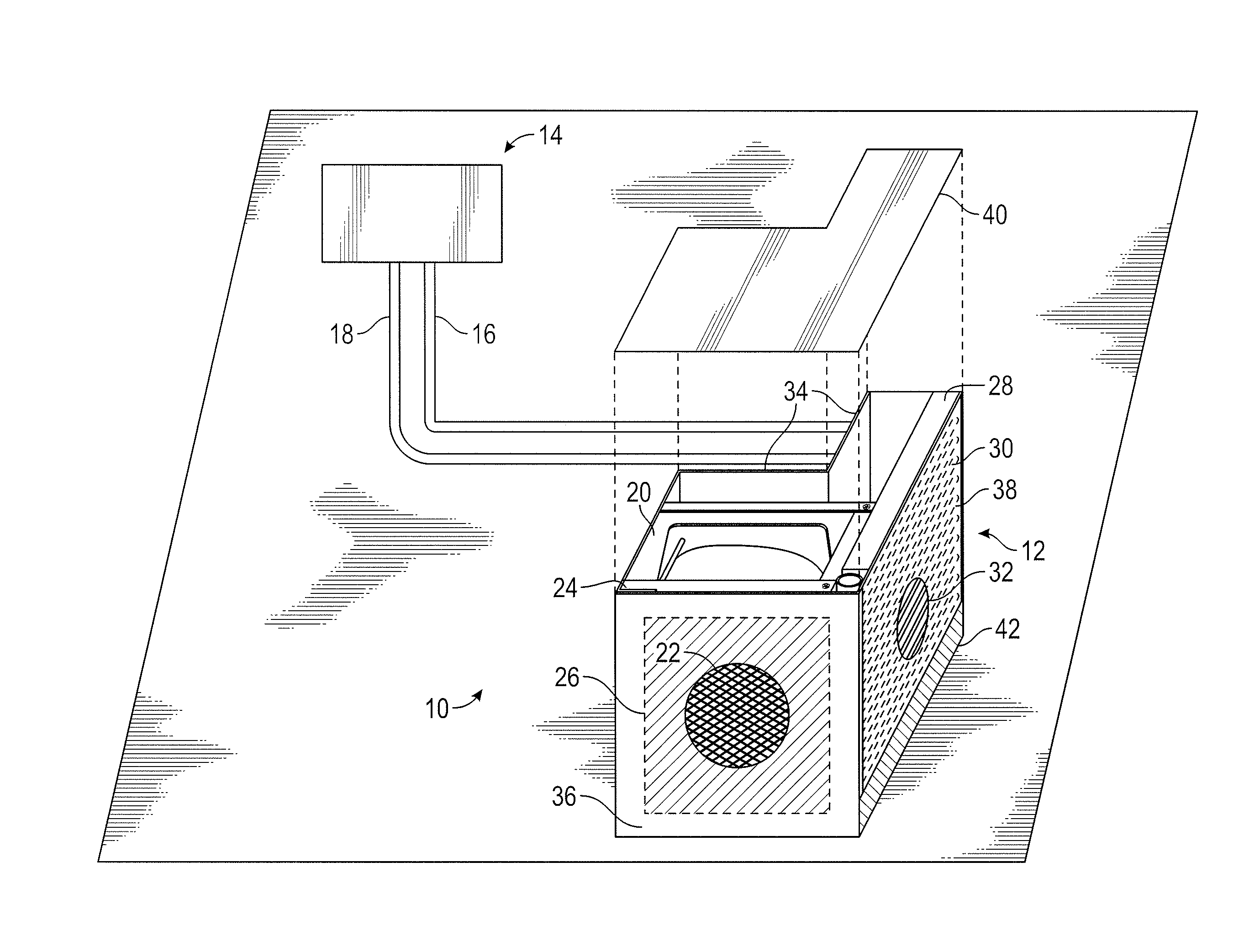
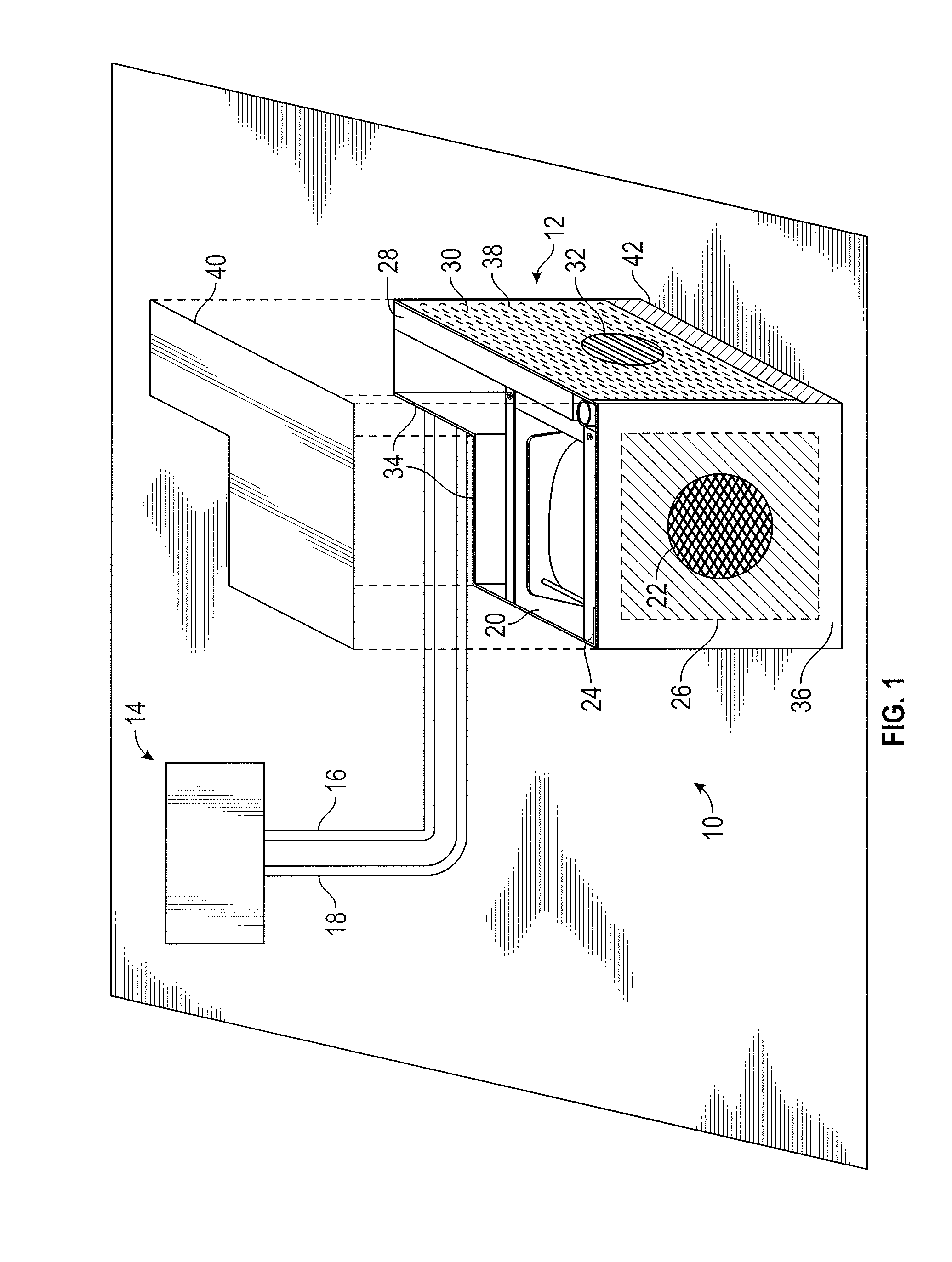
[0012]FIG. 1 illustrates a system 10 for heating and cooling a hazardous environment. A hazardous environment may be one where flammable or volatile vapors, dust or other hazardous materials are present. For such environments, heating and cooling apparatuses should reduce the possibility of electrical sparking by, for example, reducing any static buildup. As briefly summarized here and discussed in greater detail with respect to FIG. 2 below, the present embodiment achieves these technical advantages in several ways.

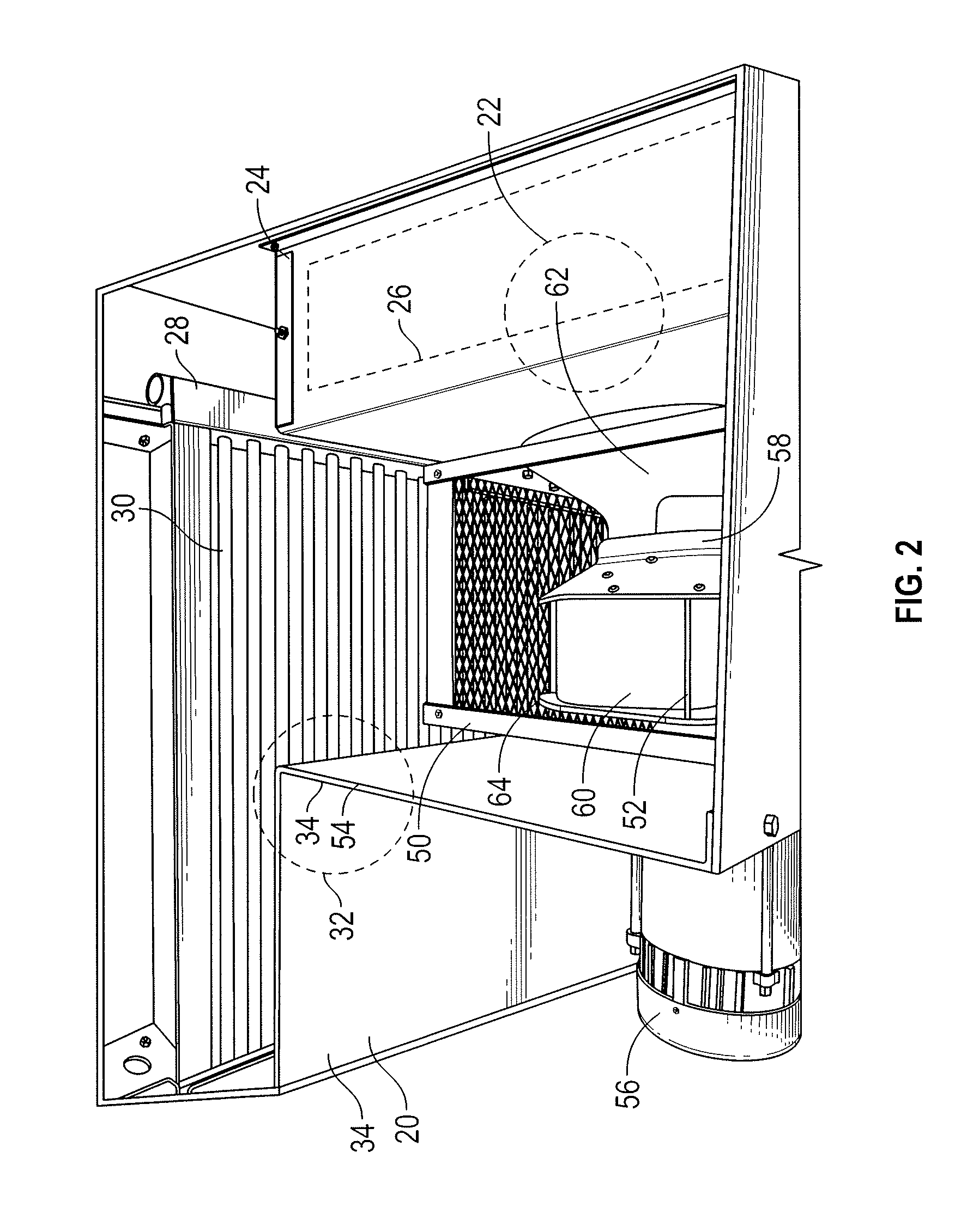
[0013]First, in the present embodiment, apparatus 12 has a motor that is partially positioned inside the housing and partially outside the housing. This configuration of the motor reduces the possibility of the motor overheating and causing electrical sparking which may be dangerous in a volatile or hazardous environment. Second, the motor of the present embodiment runs continuously when it is connected to a power source. This further reduces the possibility of electrica...


PUM


Abstract

A heating and cooling apparatus for hazardous environments is disclosed. The apparatus has a housing having an air inlet and an air outlet. The apparatus further comprises a motor having a shaft and an electrical component and a metallic impeller having an impeller inlet and blades. The impeller inlet faces the air inlet of the housing and the impeller is coupled to the shaft of the motor. The apparatus also has an air filter removably positioned at the air inlet of the housing. A coil is removably positioned inside the housing between the air outlet and the impeller blades. A valve is also coupled to the coil, the valve being operable to regulate the temperature of the coil by controlling the flow of fluid into the coil.

Description

TECHNICAL FIELD OF THE INVENTION[0001]This disclosure relates generally to electro-mechanical devices and specifically to a heating and cooling system for hazardous environments.BACKGROUND OF THE INVENTION[0002]It is often necessary to heat or cool various environments including hazardous environments. Current approaches for heating and cooling hazardous environments are dangerous and immobile. It is thus desirable to create a safe and mobile system that can heat or cool hazardous environments for suitable periods of time.SUMMARY OF THE INVENTION[0003]According to embodiments of the present disclosure, disadvantages and problems associated with previous heating and cooling systems for hazardous environments may be reduced or eliminated.[0004]In one embodiment, a heating and cooling apparatus for hazardous environments comprises a housing having an air filter insert. The housing further comprises a first wall having an air inlet and a second wall having an air outlet. The apparatus h...

Claims


Application Information

Patent Timeline
IPC IPC(8): F24F1/00F24H3/08F24F1/04
CPCF24F1/04F24F2001/0051F24H3/08F24F1/0018F24F2221/125F24F11/83F24F11/84
Inventor MYERHOLTZ, JR., ROBERT M.DANCEY, LARRY L.
Owner THERMA STOR LLC
Why Eureka
Try Eureka