
Image display device

a display device and image technology, applied in the field of image display devices, can solve the problems of not being able to accurately recognize the displayed image, the mounting member is not likely to be laid along the head, and the mounting feeling is not high, so as to facilitate the elastic deformation of the elastic member and improve the mountability of the image display devi

Inactive Publication Date: 2016-12-22
SEIKO EPSON CORP
View PDF6 Cites 31 Cited by
  • Summary
  • Abstract
  • Description
  • Claims
  • Application Information

AI Technical Summary

Benefits of technology

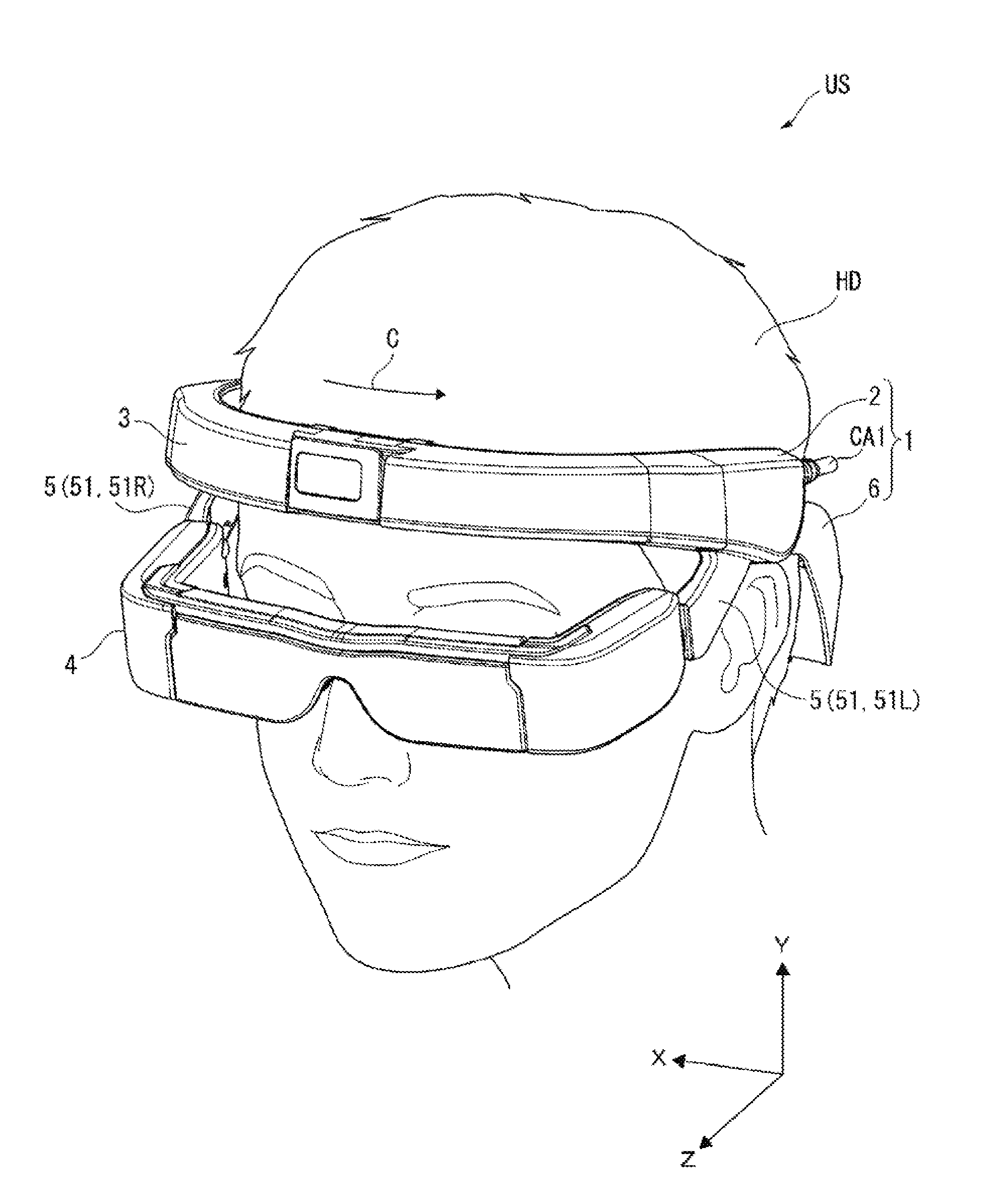
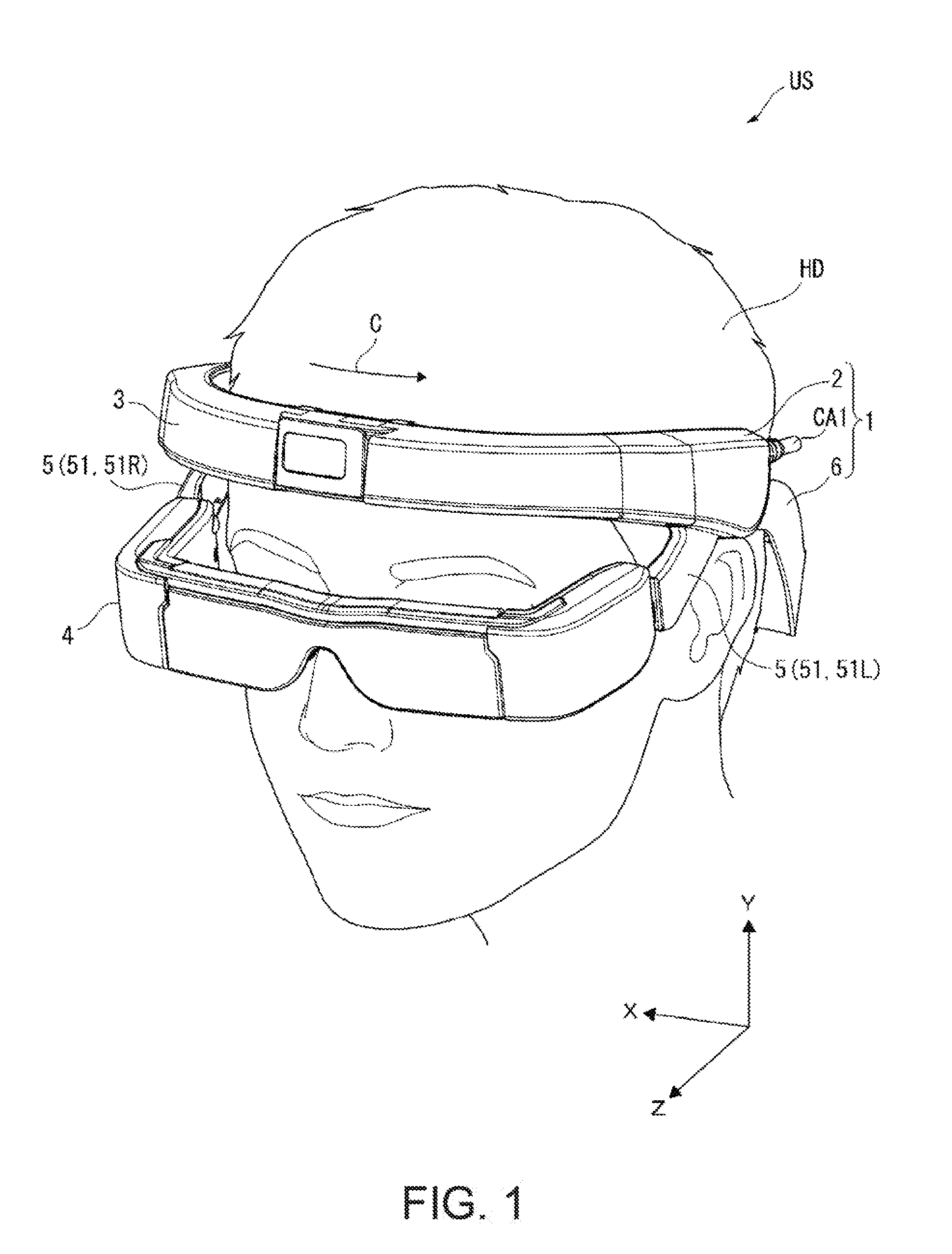
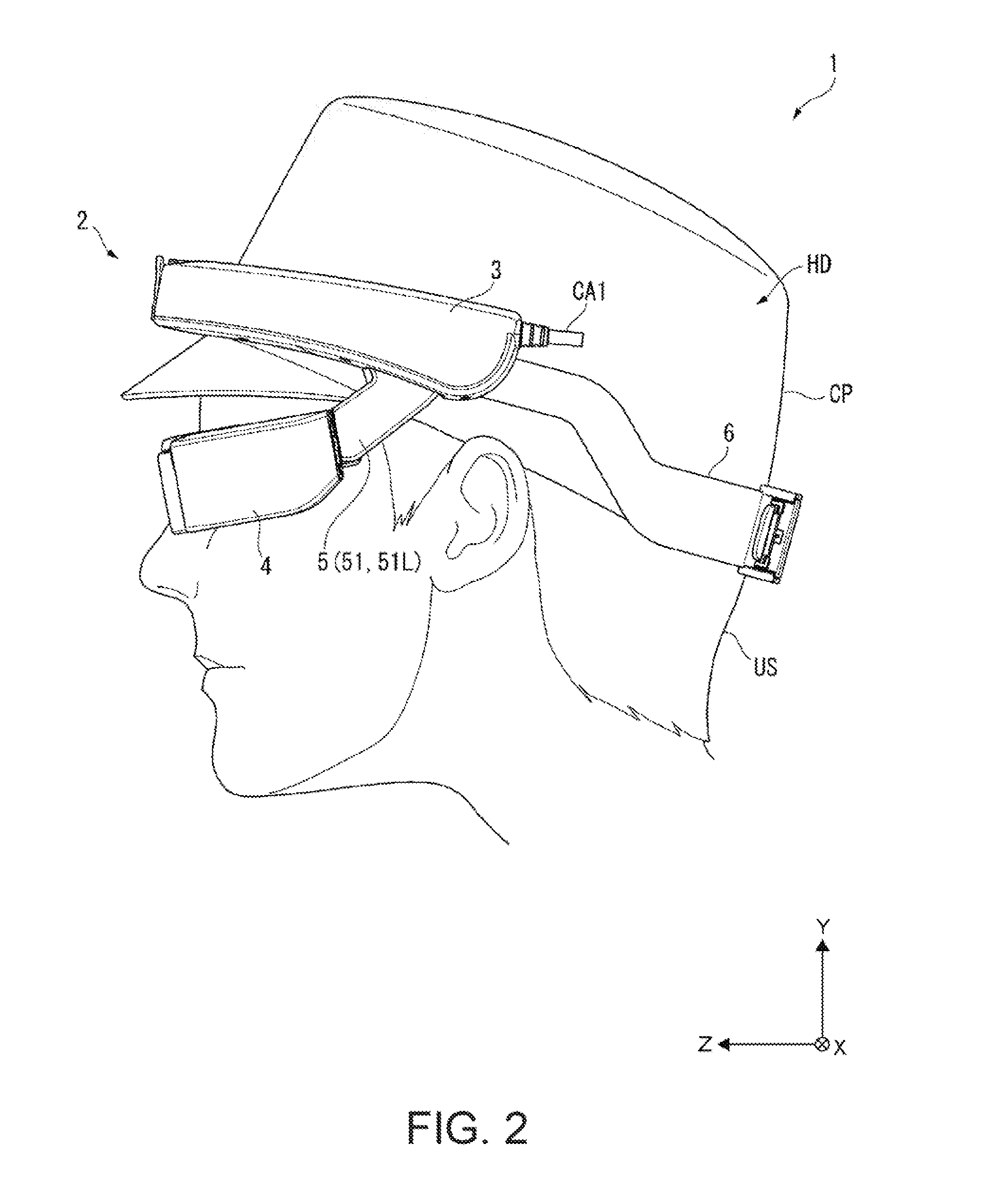
The patent aims to create an image display device that is easy to mount.

Problems solved by technology

However, in the virtual image display device disclosed in JP-A-2014-186201, the virtual image display device is supported by the temple portions and the nose pad member, and thus there is a problem in that mountability and a mounting feeling are not high.
Particularly, in a case where the user carrying out a predetermined work makes use of the virtual image display device, there may be a concern of a displayed image not being appropriately visually recognized due to a slipping or the like of the virtual image display device while at work.
In addition, even in a case where the mounting member is installed on the opposite side to the side facing the head in the frame, the mounting member is not likely to be laid along the head.
In this case, when the ears are covered with the mounting member, a burden on a user increases, and thus it is not likely that the image display device is mounted for a long period of time.

Method used


Image

  • Image display device
  • Image display device
  • Image display device

Examples


embodiment

Modification of Embodiment

[0157]The invention is not limited to the above-mentioned embodiment, but changes, modifications and the like within the range capable of achieving the object of the invention are included in the invention.

[0158]In the above embodiment, the head band portion 3 as a frame is formed in an arc shape conforming to the shape of the head HD (specifically, forehead). However, the invention is not limited thereto. For example, the head band portion 3 may be formed in a substantially rectangular parallelepiped shape. In this case, a surface facing the head HD may be formed in an arc shape conforming to the shape of the head HD. That is, the head band portion 3 may be formed in any shape. In addition, in the invention, the frame is not limited to a configuration in which the frame is disposed in accordance with the forehead, and may have a configuration in which the frame is disposed in the temporal region (for example, position located above the ear).

[0159]In the ab...


PUM


Abstract

An image display device includes a device main body which is mounted on the head of a user and a mounting member that mounts the device main body on the head. The device main body includes a frame that comes into contact with the forehead in the head and a display portion, provided in the frame, which displays an image. The mounting member, formed of a material having a predetermined hardness, which comes into contact with a contact region which is set in a lower portion in the occipital region of the head and holds the head together with the frame.

Description

BACKGROUND[0001]1. Technical Field[0002]The present invention relates to an image display device.[0003]2. Related Art[0004]Hitherto, a virtual image display device such as a head mounted display (HMD) which is mounted on the head of a user has been known (see, for example, JP-A-2014-186201).[0005]The virtual image display device disclosed in JP-A-2014-186201 includes a first image forming main body and a second image forming main body which are provided on the right and left sides of a user, respectively, and light guide members that guide image light which is formed by these image forming main bodies to the right eye and the left eye of the user, respectively, and is configured as a see-through HMD. Besides, the virtual image display device includes a frame portion provided with a nose pad member which is brought into contact with the nose of the user and temple portions, provided in the frame portion, which are brought into contact with the vicinity of the temples of the user. The...

Claims


Application Information

Patent Timeline
IPC IPC(8): G02B27/01
CPCG02B2027/0154G02B27/0176G02B2027/0178
Inventor FUJISHIRO, TAKESHI
Owner SEIKO EPSON CORP
Learn More