Lighting device, smart terminal, lighting-device network-forming system, and methods thereof

a lighting device and smart terminal technology, applied in the field of led lighting technologies, can solve the problems of reducing the network-forming efficiency of smart led lamps, complicated disassembly process,

Inactive Publication Date: 2016-12-22
SENGLED OPTOELECTRONICS
View PDF5 Cites 12 Cited by
  • Summary
  • Abstract
  • Description
  • Claims
  • Application Information

AI Technical Summary

Benefits of technology

[0008]Another aspect or embodiment of the present disclosure provides a smart terminal. The smart terminal includes a camera; a decoder; and a processing module. The camera is connected to the decoder and configured to obtain a brightness change of an LED lamp in a lighting device within a predetermined time period to generate video data to send the video data to the decoder. The decoder is connected to the camera and the processing module and configured to parse the video data sent by the camera, obtain a telegraph code corresponding to the brightness change of the LED lamp during the predetermined time period, and send the telegraph code to the processing module. The processing module is connected to the decoder and configured to look up a pre-stored correspondence relationship between the telegraph code and an identity of the LED lamp based on the telegraph code to determine the identity of the LED lamp and to form a network with the LED lamp based on the identity of the LED lamp.

Problems solved by technology

The disassembling process may be a complicated operation and the network-forming efficiency of the smart LED lamps may be reduced.

Method used


Image

  • Lighting device, smart terminal, lighting-device network-forming system, and methods thereof
  • Lighting device, smart terminal, lighting-device network-forming system, and methods thereof
  • Lighting device, smart terminal, lighting-device network-forming system, and methods thereof

Examples


Embodiment Construction

[0025]Reference will now be made in detail to exemplary embodiments of the invention, which are illustrated in the accompanying drawings. Hereinafter, embodiments consistent with the disclosure will be described with reference to drawings. Wherever possible, the same reference numbers will be used throughout the drawings to refer to the same or like parts. It is apparent that the described embodiments are some but not all of the embodiments of the present invention. Based on the disclosed embodiment, persons of ordinary skill in the art may derive other embodiments consistent with the present disclosure, all of which are within the scope of the present invention.

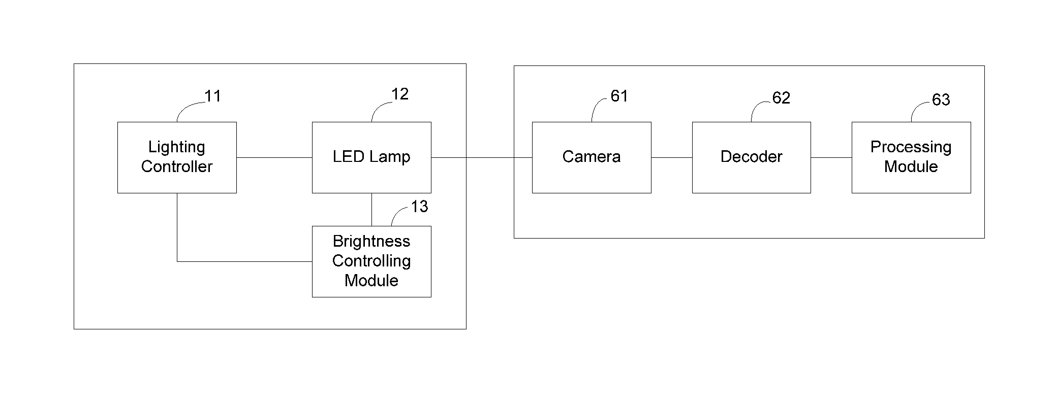
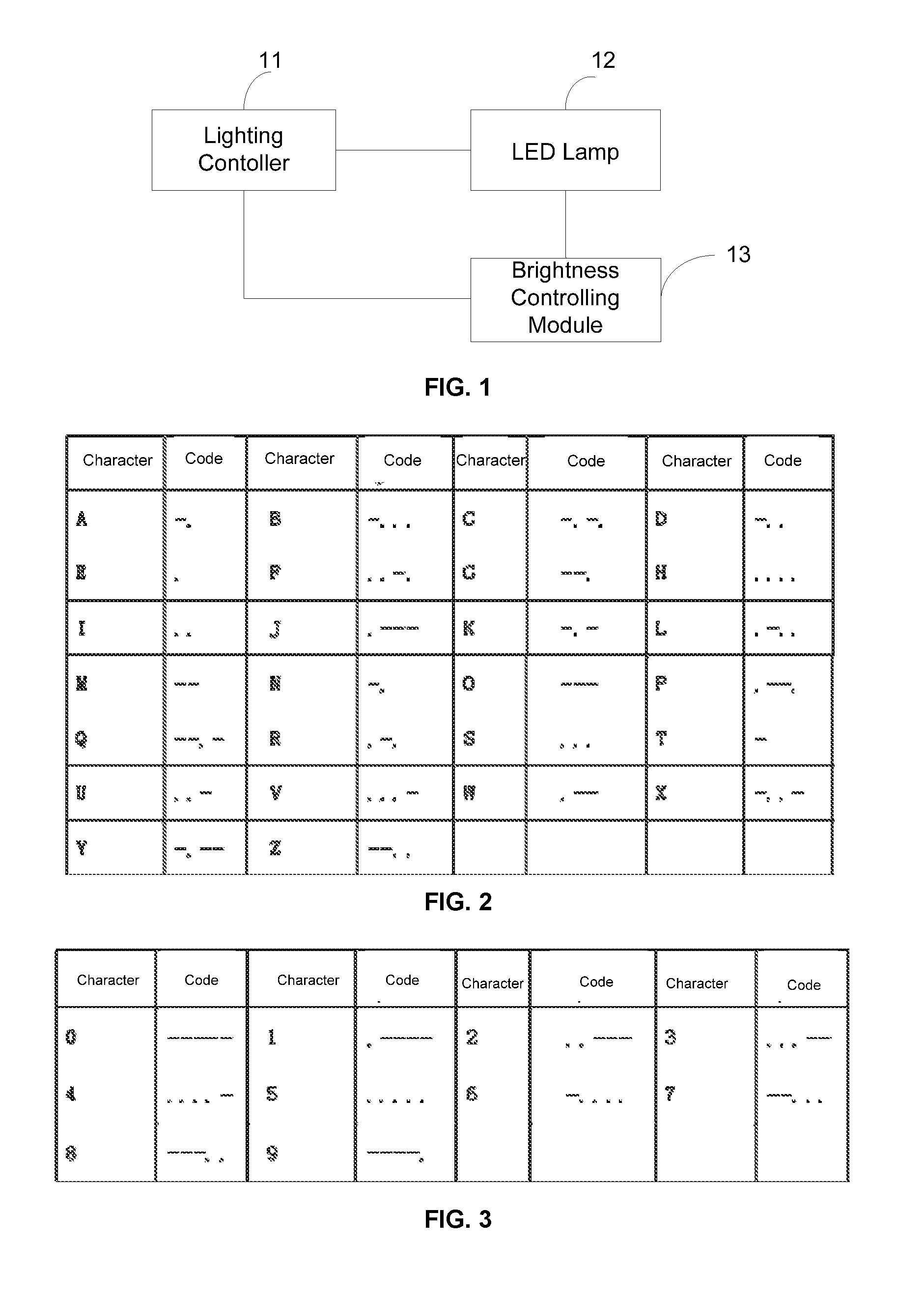
[0026]FIG. 1 illustrates an exemplary LED lighting device provided by the present disclosure. As shown in FIG. 1, the LED lighting device may include a lighting controller 11, an LED lamp 12, and a brightness controlling module 13.

[0027]The lighting controller 11 may be connected to the LED lamp 12 and the brightness control...


PUM


Abstract

The present disclosure provides a lighting device including a lighting controller, an LED lamp, and a brightness controlling module. The lighting controller is configured for sending first control signals to the LED lamp and the brightness controlling module. The first control signals include an identity of the LED lamp and instruction information for turning on and off the LED lamp. The brightness controlling module is configured for receiving the first control signals sent by the lighting controller and obtaining a previously-stored telegraph code corresponding to the identity of the LED lamp when successively receiving the first control signals instructing to turn on, off, and on the LED lamp within a predetermined time period. The brightness controlling module is configured to adjust a brightness of the LED lamp according to the telegraph code and send out the telegraph code in a manner by changing the brightness of the LED lamp.

Description

CROSS-REFERENCES TO RELATED APPLICATIONS[0001]This application claims the priority of Chinese Patent Application No. CN201410843245.0, filed on Dec. 30, 2014, the entire content of which is incorporated herein by reference.FIELD OF THE DISCLOSURE[0002]The present disclosure generally relates to the field of light emitting diode (LED) technologies and, more particularly, relates to a lighting device, a smart terminal, a lighting-device network-forming system, and methods thereof.BACKGROUND[0003]With the emergence of smart homes, LED (light emitting diode) smart lighting becomes widely used in various areas. Remotely-controlled smart LED lamps may become a standard of the smart lighting for better user experience. To realize remotely-controlled smart LED lamps and / or smart LED lamp groups, it is desirable to connect a plurality of smart LED lamps with a control terminal device in a certain manner. Multiple smart LED lamps may be grouped to form a network.[0004]Currently, transmission ...

Claims


Application Information

Patent Timeline
Patent Type & Authority Applications(United States)
IPC IPC(8): H05B33/08H05B37/02H05B44/00
CPCH05B33/0848H05B37/0227H05B33/0815H05B37/0272H05B47/19Y02B20/40H05B47/105H05B45/12H05B47/135H05B45/14
Inventor ZHENG, JIANBINGZHANG, LIRONGSHEN, JINXIANG
Owner SENGLED OPTOELECTRONICS
Why Eureka
Try Eureka