
Methods and systems for port fuel injection control

a technology of fuel injection and port, which is applied in the direction of electric control, combustion air/fuel air treatment, machines/engines, etc., can solve the problems of insufficient time, inability of direct fuel injectors to provide the desired amount of fuel to a cylinder, and engine may develop less power than is desired, so as to improve the cooling of the cylinder, less power, and higher compression ratio

Active Publication Date: 2016-12-29
FORD GLOBAL TECH LLC
View PDF14 Cites 18 Cited by
  • Summary
  • Abstract
  • Description
  • Claims
  • Application Information

AI Technical Summary

Benefits of technology

The patent describes a method for reducing particulate matter emissions and fuel dilution in an engine system with a dual fuel injection system. The method involves pressurizing fuel in both a port injection fuel rail and a direct injection fuel rail, and during certain operating conditions, fueling the engine with at least a calibrated minimum amount of port injected fuel for every combustion event. This helps to maintain low fuel temperatures and reduces the need for a temperature sensor in the fuel rail. The method also reduces fueling errors caused by vapor formation in the fuel rail. Overall, this method simplifies and reduces costs associated with temperature control in the engine system.

Problems solved by technology

However, direct fuel injectors may not be able to provide a desired amount of fuel to a cylinder at higher engine speeds and loads because the amount of time a cylinder stroke takes is shortened so that there may not be sufficient time to inject a desired amount of fuel.
Consequently, the engine may develop less power than is desired at higher engine speeds and loads.
In addition, direct injection systems may be more prone to particulate matter emissions.
However, one issue with such dual fuel injection system configurations is that during conditions when there is no fuel flowing through the port injection system (such as when only direct injection is enabled), fuel vapor can form in the port injection fuel system.
This can result in fueling errors and lean operation when port injection is enabled.
As a result, there may be non-starting engine combusting conditions where the engine is operated with partial direct injection, or with no direct injection (and only port injection).

Method used


Image

  • Methods and systems for port fuel injection control
  • Methods and systems for port fuel injection control
  • Methods and systems for port fuel injection control

Examples


Embodiment Construction

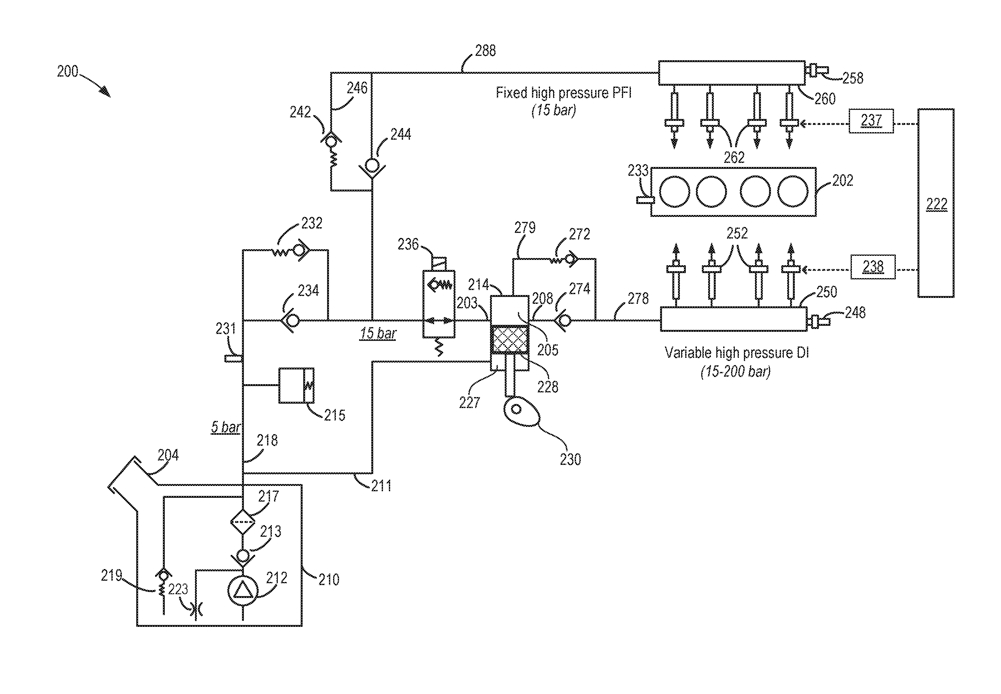
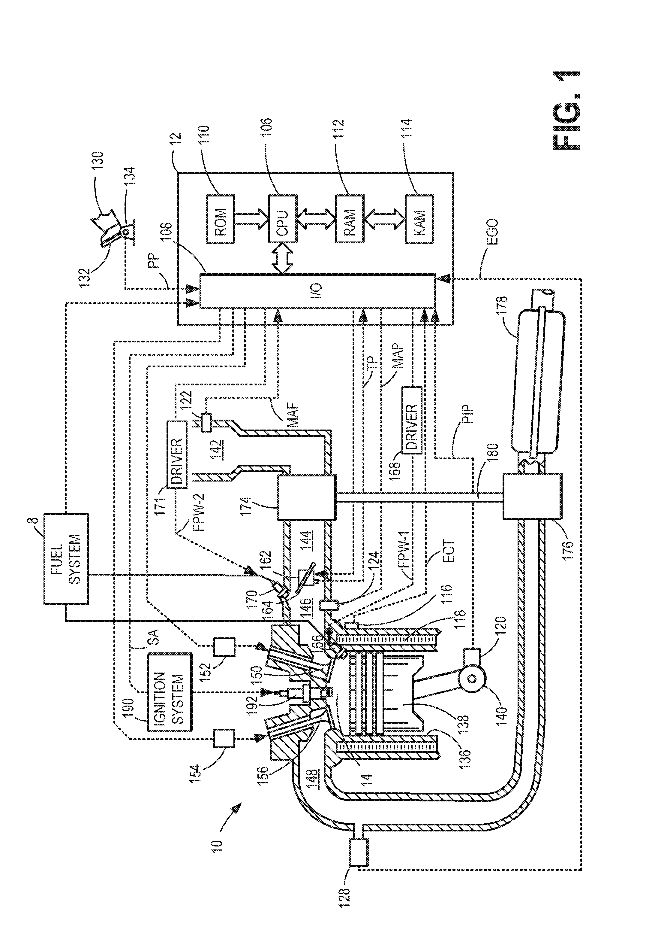
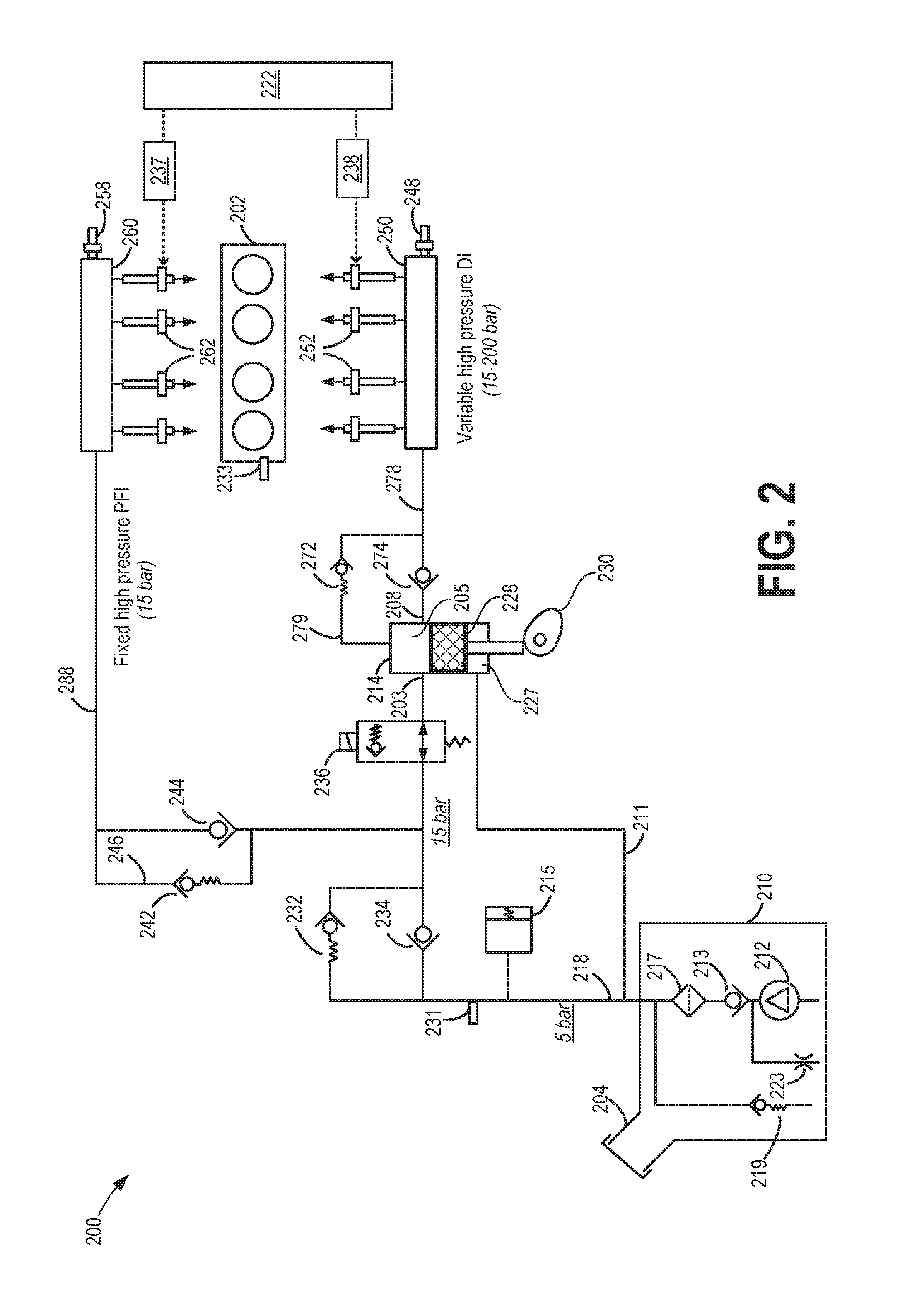
[0015]The following detailed description provides information regarding a dual fuel injection system and a method for reducing fuel vapor formation at a port injection fuel rail. An example embodiment of a cylinder in an internal combustion engine is given in FIG. 1 while FIG. 2 depicts an example fuel system that may be used with the engine of FIG. 1. A controller may be configured to perform a control routine, such as the example routine of FIGS. 3A-3B, to adjust a port fuel injection amount based on engine speed-load conditions based on input from a calibrated map (FIG. 4), and independent of fuel rail temperature, to reduce fuel vapor formation at the port injection rail. An example port fuel injection adjustment is shown at FIG. 5.

[0016]Regarding terminology used throughout this detailed description, a high pressure pump, or direct injection pump, may be abbreviated as a DI or HP pump. Similarly, a low pressure pump, or lift pump, may be abbreviated as a LP pump. Port fuel inje...


PUM


Abstract

Methods and systems are provided for reducing hot fuel vapor formation in a port injection fuel rail. In one example, a method may include operating a dual fuel injection system with at least a calibrated minimum amount of port fuel injection over a wide range of engine operating conditions, even as conditions change. A direct fuel injection amount is adjusted in accordance.

Description

CROSS REFERENCE TO RELATED APPLICATION[0001]The present application claims priority to U.S. Provisional Patent Application No. 62 / 186,171, entitled “Methods and Systems for Port Fuel Injection Control,” filed on Jun. 29, 2015, the entire contents of which are hereby incorporated by reference for all purposes.FIELD[0002]The present description relates to systems and methods for adjusting operation of an internal combustion engine that includes high pressure port and direct fuel injectors.BACKGROUND AND SUMMARY[0003]Direct fuel injection (DI) systems provide some advantages over port fuel injection systems. For example, direct fuel injection systems may improve cylinder charge cooling so that engine cylinders may operate at higher compression ratios without incurring undesirable engine knock. However, direct fuel injectors may not be able to provide a desired amount of fuel to a cylinder at higher engine speeds and loads because the amount of time a cylinder stroke takes is shortened ...

Claims


Application Information

Patent Timeline
IPC IPC(8): F02D41/38F02D41/30F02D41/00F02M63/02
CPCF02D41/3854F02M63/0285F02D2041/3881F02D41/3094F02D41/0097F02M63/0265F02D41/38F02M35/104F02D41/221F02D19/084F02D2041/224F02M63/029F02M2200/956F02M69/046F02M2200/95Y02T10/30
Inventor RUSS, STEPHEN GEORGETHOMAS, JOSEPH LYLELEHTO, SCOTT ALLANWOODRING, CHRISTOPHER ARNOLDWEI, JEANNESHELLEY, DAVID
Owner FORD GLOBAL TECH LLC
Learn More