Integrated Circuit and Switching Power-Supply Device

Active Publication Date: 2016-12-29
SANKEN ELECTRIC CO LTD
View PDF2 Cites 9 Cited by
  • Summary
  • Abstract
  • Description
  • Claims
  • Application Information

AI Technical Summary

Benefits of technology

[0006]According to the disclosure, it is possible to provide the switching power-supply device and the integrated circuit for the switching power-supply dev

Problems solved by technology

As a result, a switching loss or a switching noise increases, s

Method used


Image

  • Integrated Circuit and Switching Power-Supply Device
  • Integrated Circuit and Switching Power-Supply Device
  • Integrated Circuit and Switching Power-Supply Device

Examples


first modified embodiment

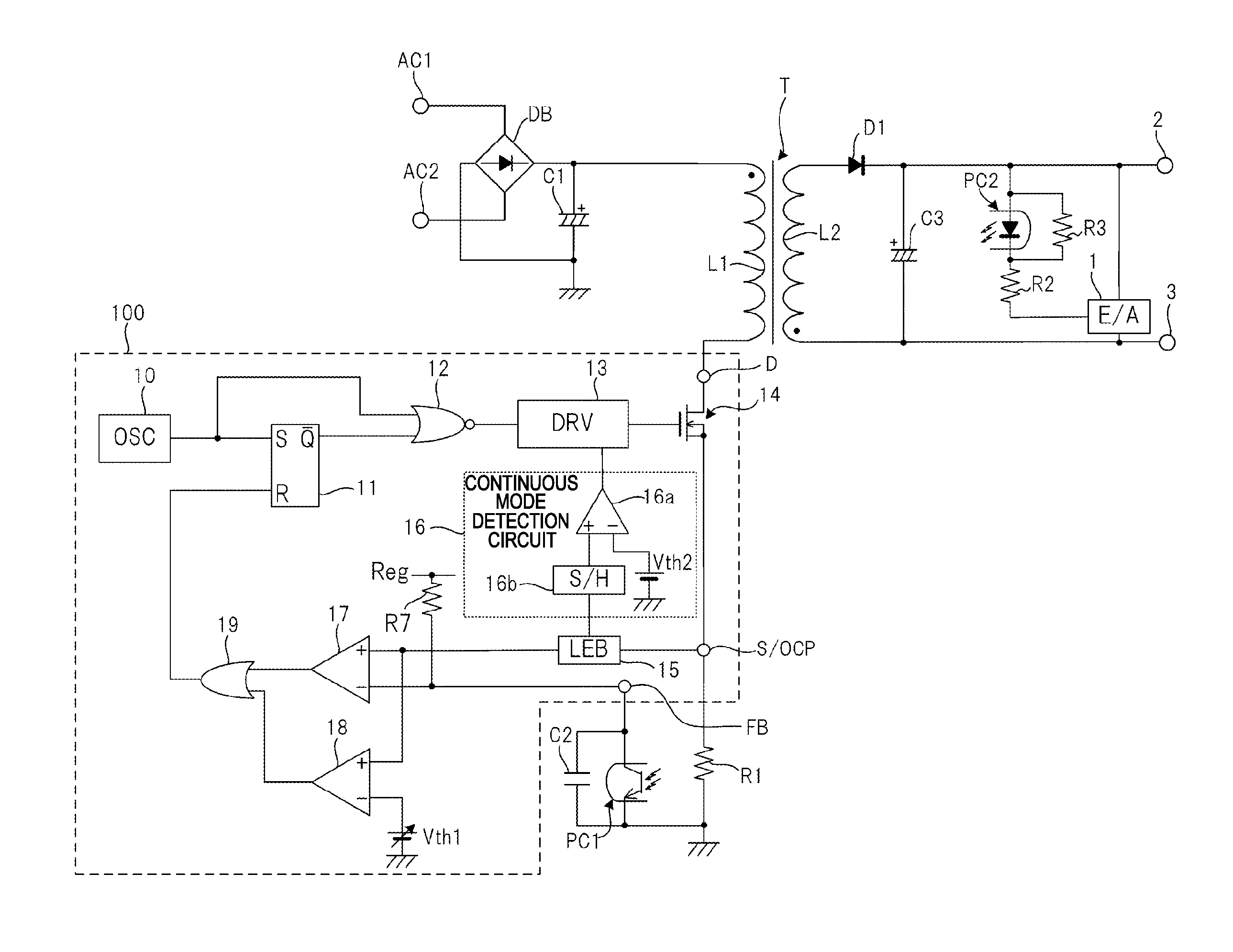
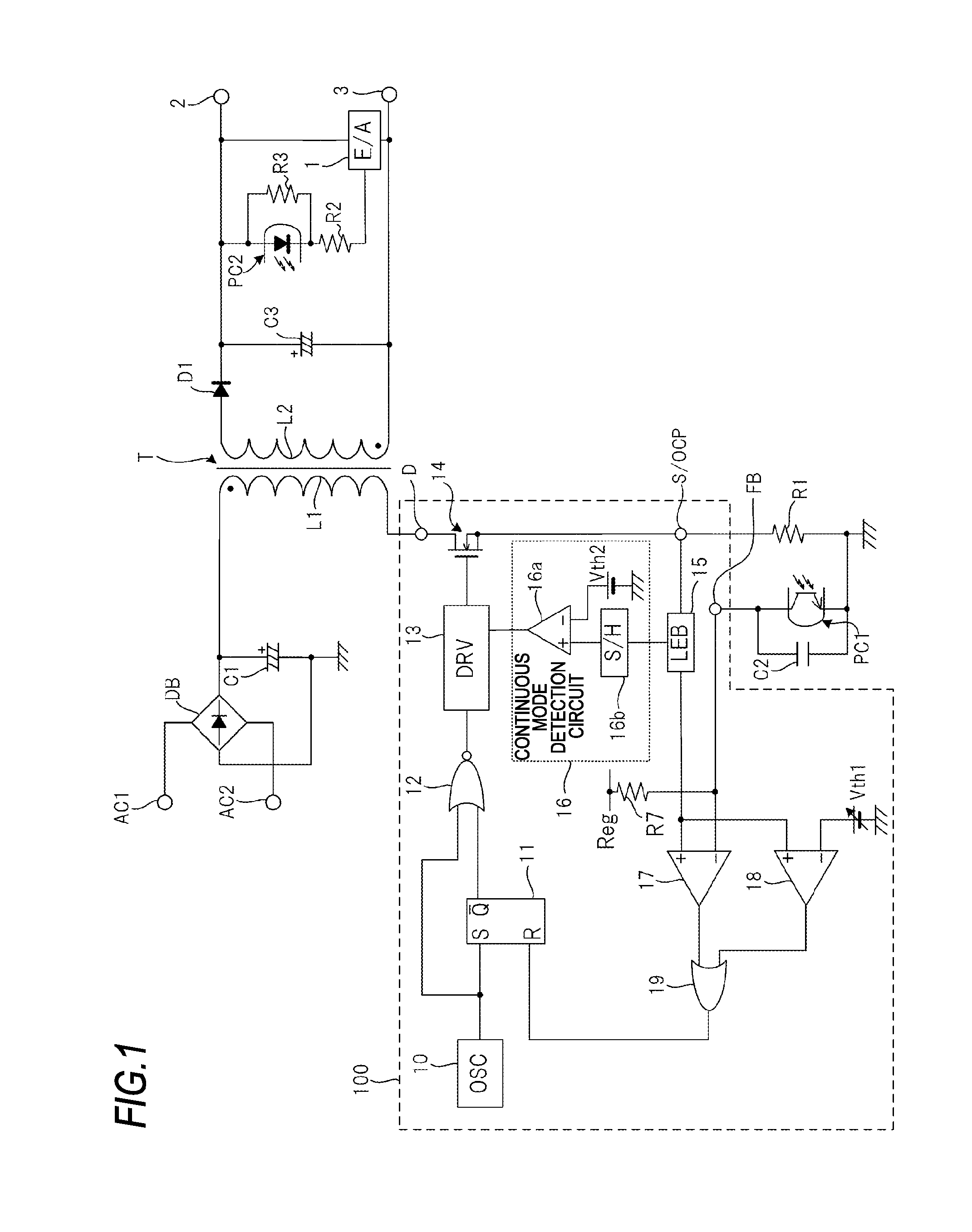
[0084]FIG. 5 shows the switching power-supply device shown in FIG. 1.

[0085]The switching power-supply device show in FIG. 5 has the same configuration as the switching power-supply device shown in FIG. 1, except that the configurations of the OSC 10 and the DRV 13 are partially changed and the output of the comparator 16a is input to the OSC 10.

[0086]The OSC 10 of the switching power-supply device shown in FIG. 5 is configured to control charging and discharging timings of a capacitor Cs, thereby varying an oscillation frequency. The DRV 13 of the switching power-supply device shown in FIG. 5 is a general driving circuit of which the drive speed is fixed.

[0087]In the switching power-supply device shown in FIG. 5, the controller IC 100 changes the switching frequency of the switching element 14 when it is detected that the output voltage control is performed in the continuous mode and a case where it is not detected that the output voltage control is performed in the continuous mode....

second modified embodiment

[0095]FIG. 7 shows the switching power-supply device shown in FIG. 1. The switching power-supply device shows in FIG. 7 has the same configuration as the switching power-supply device shown in FIG. 5, except that a counter 10a and an AND circuit 10b are added.

[0096]To the counter 10a, the output signal of the comparator 16a and the output signal of the NOR circuit 12 are input. When the output signal of the comparator 16a becomes a high level, the counter 10a counts a time until two switching cycles of the switching element 14 elapse in accordance with the output signal of the NOR circuit 12 and outputs a high-level signal during the count time period.

[0097]To the AND circuit 10b, the output signal of the counter 10a and the output signal of the NOR circuit 12 are input. The AND circuit 10b is configured to output a pulse signal in synchronization with the rising of the output signal of the NOR circuit 12 during a time period for which the output signal of the counter 10a is the hig...


PUM


Abstract

A switching power-supply device has an inductor, a switching element serially connected to the inductor, a control circuit, which controls on and off of the switching element and performs an output voltage control in any one of a plurality of modes including a continuous mode and a discontinuous mode, and a continuous mode detection circuit, which detects that the output voltage control is performed in the continuous mode when a current flowing through the switching element is equal to or greater than a threshold.

Description

TECHNICAL FIELD[0001]The disclosure relates to a switching power-supply device configured to perform an output voltage control by a switching operation, and an integrated circuit used for the same.BACKGROUND ART[0002]In a switching power-supply device configured to perform an output voltage control by a switching operation of a switching element connected to an inductor, a discontinuous mode, where the switching element is turned off and is then turned on after the current flowing through the inductor becomes zero, and a continuous mode, where the switching element is turned off and is then turned on before discharging of the accumulated energy of the inductor is completed and thus the current is enabled to continuously flow through the inductor are switched, depending on an input voltage and a state of load.SUMMARY[0003]As described above, according to the configuration where the continuous mode and the discontinuous mode are switched, the switching power-supply device may operate ...

Claims


Application Information

Patent Timeline
IPC IPC(8): H02M1/088H03K17/687H02M3/335
CPCH02M1/088H02M2001/0054H03K17/687H02M3/33507H02M7/2176H02M7/219H02M1/0048H03K17/166H02M1/0054Y02B70/10H02M1/0029
Inventor HAYAKAWA, AKIRAYOSHINAGA, MITSUTOMO
Owner SANKEN ELECTRIC CO LTD
Why Eureka
Try Eureka