Screw, injection molding machine, and injection molding method

a technology of injection molding machine and fiber reinforced resin, which is applied in the direction of coatings, etc., can solve the problems of cutting of reinforcing fibers, inability to uniformly disperse reinforcing fibers in fiber reinforced resin, and the obtained molded products cannot possibly meet desired characteristics, etc., and achieves the effect of eliminating uneven distribution of reinforcing fibers

Active Publication Date: 2017-01-05
U MHI PLATECH CO LTD +1
View PDF4 Cites 3 Cited by
  • Summary
  • Abstract
  • Description
  • Claims
  • Application Information

AI Technical Summary

Benefits of technology

[0024]According to the present invention, there can be provided the screw of the injection molding machine that can eliminate uneven distribution of the reinforcing fibers without giving an excessive shear force to the reinforcing fibers.

Problems solved by technology

Although mixing conditions may just be made severe to strengthen a shear force given to reinforcing fibers in order to achieve uniform dispersion, an excessively strong shear force causes cutting of the reinforcing fibers.
In that case, a fiber length after molding might be significantly shorter than an original fiber length, and obtained molded products cannot possibly satisfy desired characteristics (Patent Literature 1).
In that case, the reinforcing fibers cannot be uniformly dispersed in fiber reinforced resin, and are unevenly distributed.
Particularly, in a case where a contained amount of the reinforcing fibers is high, i.e. not less than 10%, it is difficult to uniformly disperse the reinforcing fibers in the resin.

Method used


Image

  • Screw, injection molding machine, and injection molding method
  • Screw, injection molding machine, and injection molding method
  • Screw, injection molding machine, and injection molding method

Examples


first embodiment

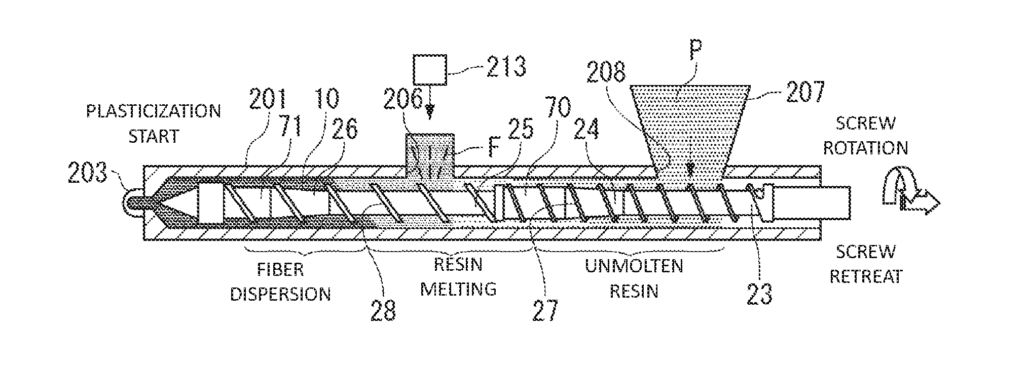
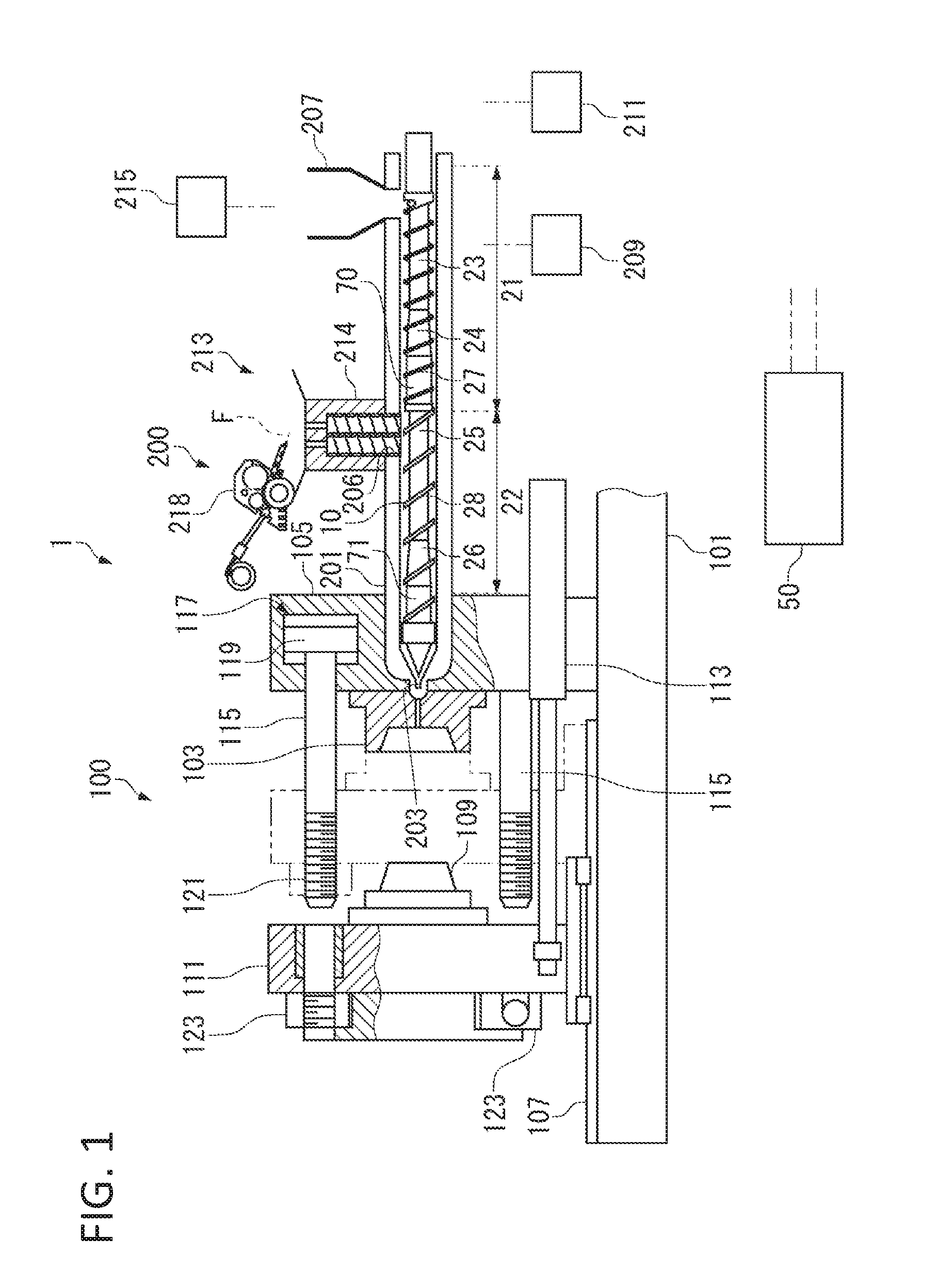
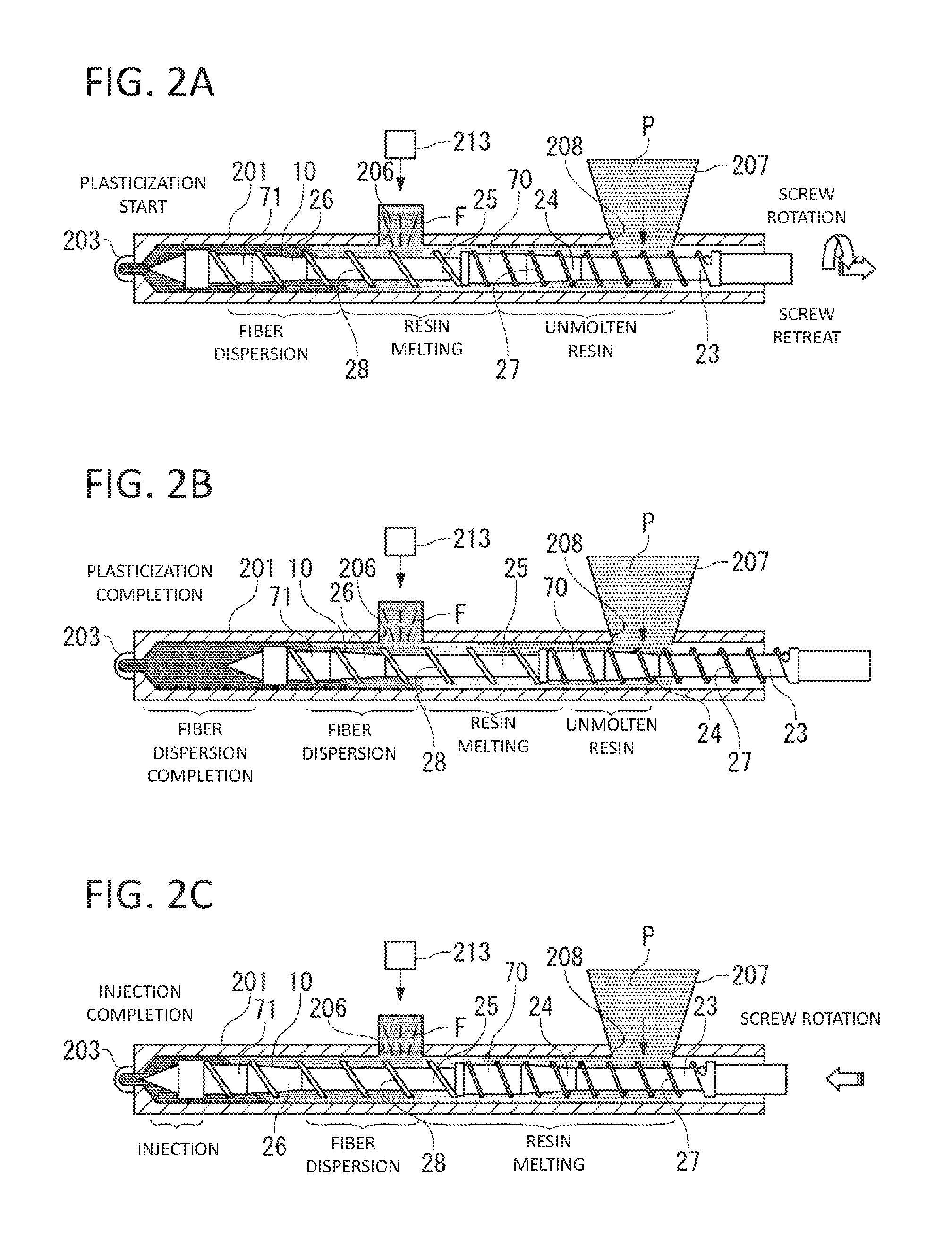
[0034]An injection molding machine 1 according to the embodiment, as shown in FIG. 1, includes: a mold clamping unit 100; a plasticizing unit 200; and a control unit 50 that controls operations of the units.

[0035]Hereinafter, outlines of a configuration and an operation of the mold clamping unit 100, and a configuration and an operation of the plasticizing unit 200 will be explained, and next, procedures of injection molding by the injection molding machine 1 will be explained.

[Configuration of Mold Clamping Unit]

[0036]The mold clamping unit 100 includes: a fixed die plate 105 that has been fixed on a base frame 101 and to which a fixed mold 103 has been attached; a movable die plate 111 that moves on a slide member 107, such as a rail and a slide plate in a left and right direction in FIG. 1 by actuating a hydraulic cylinder 113, and to which a movable mold 109 has been attached; and a plurality of tie bars 115 that couple the fixed die plate 105 with the movable die plate 111. At ...

second embodiment

[0080]Although the screw with a single-thread flight, a so-called single-flight screw, has been explained in the first embodiment, double flight with a two-thread flight including the main flight and the sub-flight can be applied to the second stage 22. Hereinafter, a screw to which the double flight is applied will be explained as a second embodiment. The second embodiment includes a second-first mode in which the double flight is applied to a portion to which the reinforcing fibers F are fed, and a second-second mode in which the double flight is applied to a downstream region away from the portion to which the reinforcing fibers F are fed.

[0081]Note that regarding the second flight 28 in the first embodiment to be included in the main flight, hereinafter, the second flight 28 shall be read as the main flight 28, and the sub-flight is represented as a sub-flight 29. As for the other components, portions different from the first embodiment will be mainly explained hereinafter, whil...

third embodiment

[0105]Although in the first embodiment and the second embodiment, examples have been explained where the resin passage in which the backflow of the melted resin raw material is generated is continuously provided in the predetermined range in the winding direction of the flight, the resin passage can be provided at a part of the winding direction of the flight in the present invention. Hereinafter, a screw in which the resin passage is applied to the part of the winding direction of the flight will be explained as a third embodiment.

[0106]Note that hereinafter, portions different from the first embodiment will be mainly explained, while citing the same symbols as in the first embodiment for the same components as in the first embodiment.

[0107]In a screw 10F according to the third embodiment, as shown in FIG. 7A, a notch 75 is provided in a part of the second flight 28, and a flight 28C of the upstream side and a flight 28D of the downstream side that are divided by the notch 75 are i...


PUM

PropertyMeasurementUnit
pressureaaaaaaaaaa
sizeaaaaaaaaaa
sizeaaaaaaaaaa

Abstract

There is provided a screw of an injection molding machine that can eliminate uneven distribution of reinforcing fibers without giving an excessive shear force to the reinforcing fibers. A screw is provided inside a heating cylinder of an injection molding machine to which a resin pellet is fed on an upstream side in a conveyance direction of resin and to which reinforcing fibers are fed on a downstream side therein, and includes: a first stage at which the resin pellet which is fed is melted; and a second stage that continues to the first stage, and at which molten resin and the reinforcing fibers are mixed with each other. A second flight provided at the second stage includes: a large-diameter flight with a relatively large outer diameter; and a small-diameter flight with a relatively small outer diameter.

Description

TECHNICAL FIELD[0001]The present invention relates to injection molding of resin containing reinforcing fibers.BACKGROUND ART[0002]There have been used for various applications molded products of fiber reinforced resin in which strength have been enhanced by making them contain reinforcing fibers. As a technique to obtain the molded product by injection molding, a technique has been known in which thermoplastic resin is melted by rotation of a screw in a cylinder serving as a plasticizing device, fibers are mixed in or kneaded with the melted thermoplastic resin, and subsequently, the thermoplastic resin is injected into a mold of an injection molding machine.[0003]In order to obtain an effect of improved strength by reinforcing fibers, the reinforcing fibers are desired to be uniformly dispersed in resin. Although mixing conditions may just be made severe to strengthen a shear force given to reinforcing fibers in order to achieve uniform dispersion, an excessively strong shear forc...

Claims


Application Information

Patent Timeline
Patent Type & Authority Applications(United States)
IPC IPC(8): B29C45/47B29C45/00B29C45/60
CPCB29C45/47B29C45/60B29C45/0005B29K2105/12B29B7/905B29B7/48B29B7/726B29B7/603B29B7/826B29C45/50B29K2105/0067
Inventor KARIYA, TOSHIHIKONOBUTA, MUNEHIROTODA, NAOKIKINOSHITA, KIYOSHIYAMAGUCHI, TAKESHI
Owner U MHI PLATECH CO LTD
Why Eureka
Try Eureka