Stacker crane

a technology of a crane and a rack is applied in the field of a rack crane, which can solve the problems of increasing the cost of the belt conveyor, the deterioration of the cost increase, so as to improve the space efficiency of the rack, improve the strength of the first mast, and reduce the cost of equipmen

Inactive Publication Date: 2017-01-05
MURATA MASCH LTD
View PDF7 Cites 9 Cited by
  • Summary
  • Abstract
  • Description
  • Claims
  • Application Information

AI Technical Summary

Benefits of technology

[0016]For this reason, by making the thickness of the sheet metal mast of the first mast larger than the thickness of the sheet metal mast of the second mast, it is possible to improve the strength of the first mast to which a load due to its self-weight is likely to be applied.
[0017]According to various preferred embodiments of the present invention, it is possible to improve the space efficiency of the rack and reduce the cost for equipment using the stacker crane, without complicating the structures of the masts and the platform.

Problems solved by technology

Hence, a space for entry of the stacker crane is required by reducing an effective space for the rack for mounting articles, thus causing a problem of deterioration in space efficiency of the rack.
This causes a problem of increasing cost for the belt conveyor.
This causes complicated structures of the masts and the platform, thus leading to a cost increase.

Method used


Image

  • Stacker crane
  • Stacker crane
  • Stacker crane

Examples


Embodiment Construction

[0025]Hereinafter, stacker cranes according to preferred embodiments of the present invention will be described with reference to the drawings. The drawings are schematic, and do not always illustrate the stacker cranes exactly.

[0026]In addition, preferred embodiments which will be described below illustrates specific examples of the present invention. Values, shapes, materials, components, arranged positions and connected states of the components, assembling method, and assembling order which will be illustrated in the following preferred embodiments are examples, and are not intended to limit the present invention. Further, the components in the preferred embodiments which are not recited in the independent claim representing a generic concept will be described as optional components.

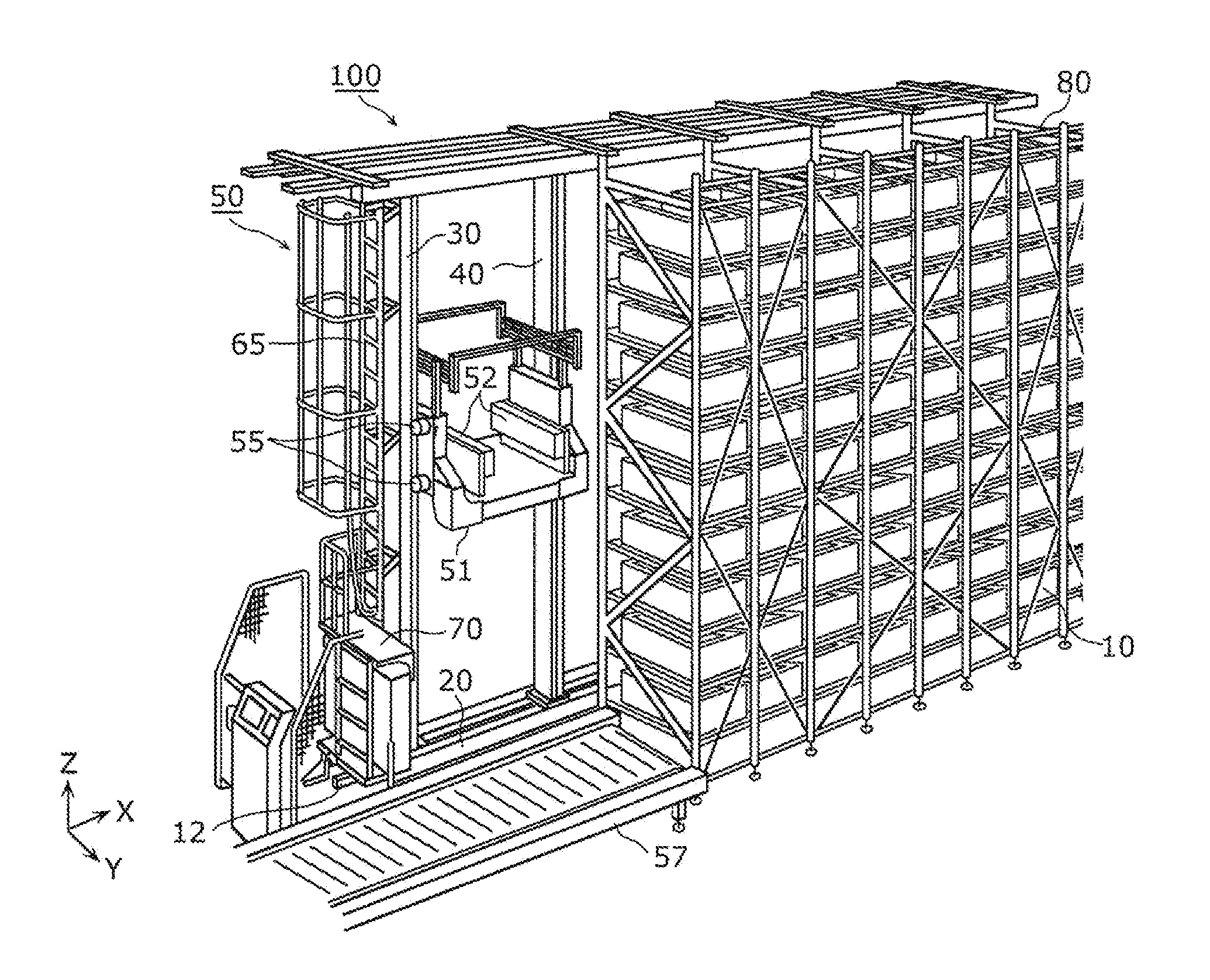
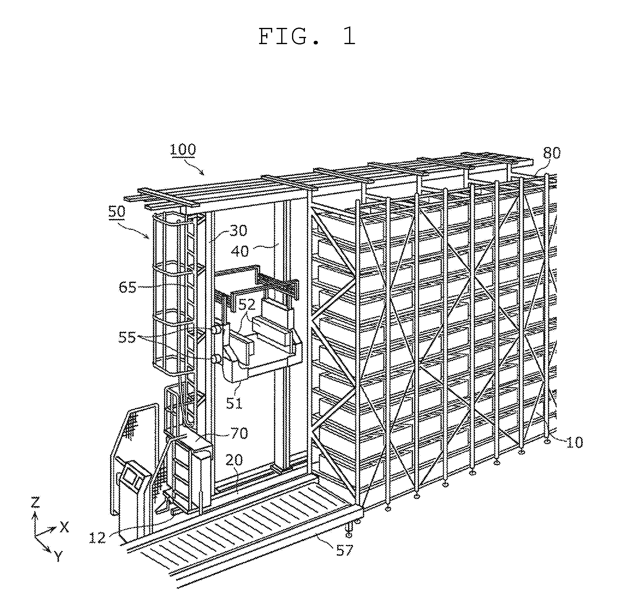
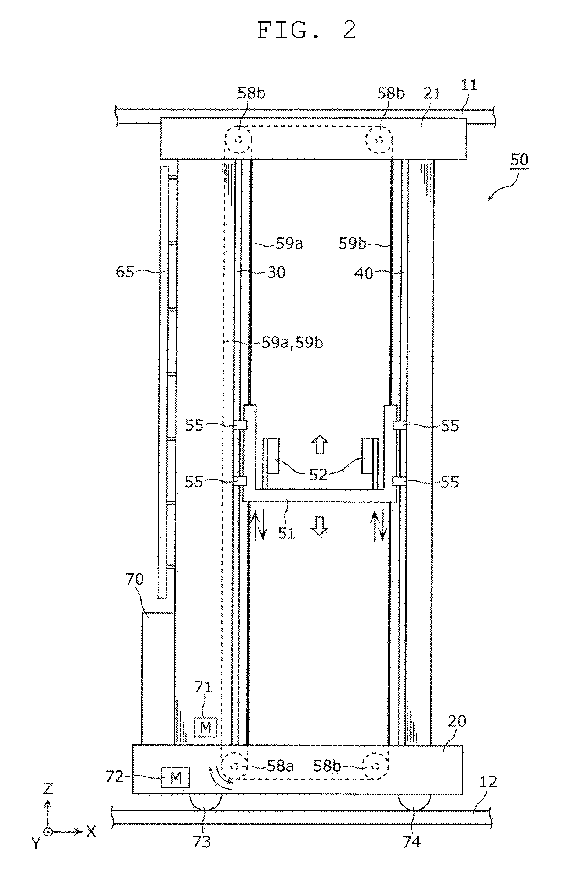
[0027]First, with reference to FIGS. 1 and 2, the outline of configurations of an automated storage 100 and a stacker crane 50 according to a preferred embodiment of the present invention will be desc...


PUM


Abstract

A stacker crane capable of improving space efficiency of a rack, and reducing cost for equipment using the stacker crane, without complicating structures of masts and a platform, includes a truck frame that travels on a track along a rack, a mast provided on the truck frame, and a platform that is raised and lowered along the mast. The mast includes a first mast that guides the platform, and a second mast located such that the platform is sandwiched between the first mast and the second mast in a travelling direction of the truck frame. As compared with the first mast, the second mast has a small width in the travelling direction of the truck frame, and has the same width as seen from the travelling direction.

Description

BACKGROUND OF THE INVENTION[0001]1. Field of the Invention[0002]The present invention relates to a stacker crane including a platform that is raised and lowered along a mast on a truck frame.[0003]2. Description of the Related Art[0004]A conventional stacker crane includes a rack capable of mounting a plurality of articles thereon, wherein the articles are mounted on the rack and are taken out therefrom. The stacker crane includes, for example, a truck frame that travels on a rail provided on a floor surface along a rack, and a mast on the truck frame. An article is passed between the stacker crane and the rack by using a transferring device provided on a platform that is raised and lowered along the mast (cf. Japanese Unexamined Patent Publication No. 2014-24658).[0005]In the technique of Japanese Unexamined Patent Publication No. 2014-24658, two masts are provided on the truck frame to guide vertical movement of the platform while supporting a load from the platform. Since the two...

Claims


Application Information

Patent Timeline
Patent Type & Authority Applications(United States)
IPC IPC(8): B65G1/04B66F9/07
CPCB66F9/07B65G1/0407
Inventor FUKAYAMA, MITSUAKI
Owner MURATA MASCH LTD
Why Eureka
Try Eureka