Point detector overtie structure

a point detector and overtie technology, applied in railway signalling, transportation and packaging, roads, etc., can solve the problems of inability to support and stabilize the rails passing over the cribs, the malfunction of the control used to determine the proper switching of the points, and the fouling of the crib or the channel holding the indicator or the rod over time. to prevent potential damage to the indicator rod

Active Publication Date: 2017-01-05
ARNOLD JAMES
View PDF0 Cites 5 Cited by
  • Summary
  • Abstract
  • Description
  • Claims
  • Application Information

AI Technical Summary

Benefits of technology

[0018]A further object of the present invention is to provide a railroad track switching apparatus which prevents potential damage to the indicator rods due to interaction with the ballast of the railroad bed.
[0019]A further object of the present invention is to provide a railroad track switching apparatus which allows proper tamping of the ballast of the railroad bed without damage to the indicator rods and throw rods.

Problems solved by technology

The absence of ballast around indicator rods found in such cribs provides access to the same, but the absence of ballast also causes lack of support and stability of the rails passing over the cribs.
Moreover, fouling of cribs or channels holding indicator or rods occurs over time.
In addition, thermal expansion and contraction of rails and movement of associated points tends to undermind the adjacent ties and requires special technique to tamp ballast in the near vicinity of such ties.
Also, the thermal expansion and contraction of the rails and points often causes misalignment of the indicator rods and the detectors and may cause malfunction of controls used to determine the proper switching of the points.
However, such channels lie below grade and suffer many of the problems in the prior art in that the ballast used on track beds tends to foul and damage the indicator rods and the channels themselves.

Method used


Image

  • Point detector overtie structure
  • Point detector overtie structure
  • Point detector overtie structure

Examples


Embodiment Construction

[0030]Various aspects of the present invention will evolve from the following detailed description of the preferred embodiments thereof which should be referenced to the prior described drawings.

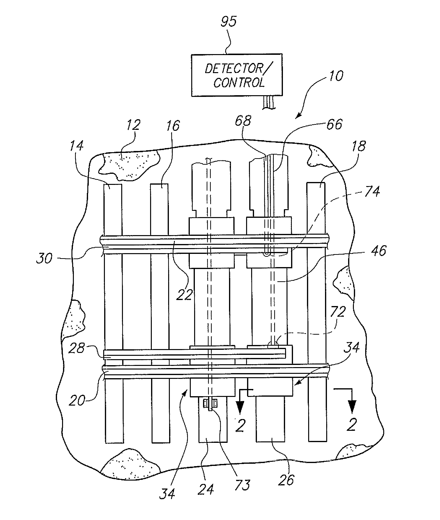
[0031]An embodiment of the invention as a whole is depicted in the drawing by reference character 10, FIGS. 1 and 6, in particular. With reference to FIG. 1, it may be observed that a ballast railroad bed 12 supports conventional ties 14, 16, and 18. Rails 20 and 22 are in turn supported by ties 14, 16, and 18. Bed 12 ballast is usually composed of gravel or other aggregate material which requires tamping to maintain the stability of bed 12. Also, depicted in FIG. 1, are ties 24 and 26 which form part of the apparatus 10 of the present invention. Further, moveable points or rails 28 and 30 are shown in relation to rails 20 and 22. As heretofore described, points 28 and 30 are employed in the switching of railroad cars on rails 20 and 22.

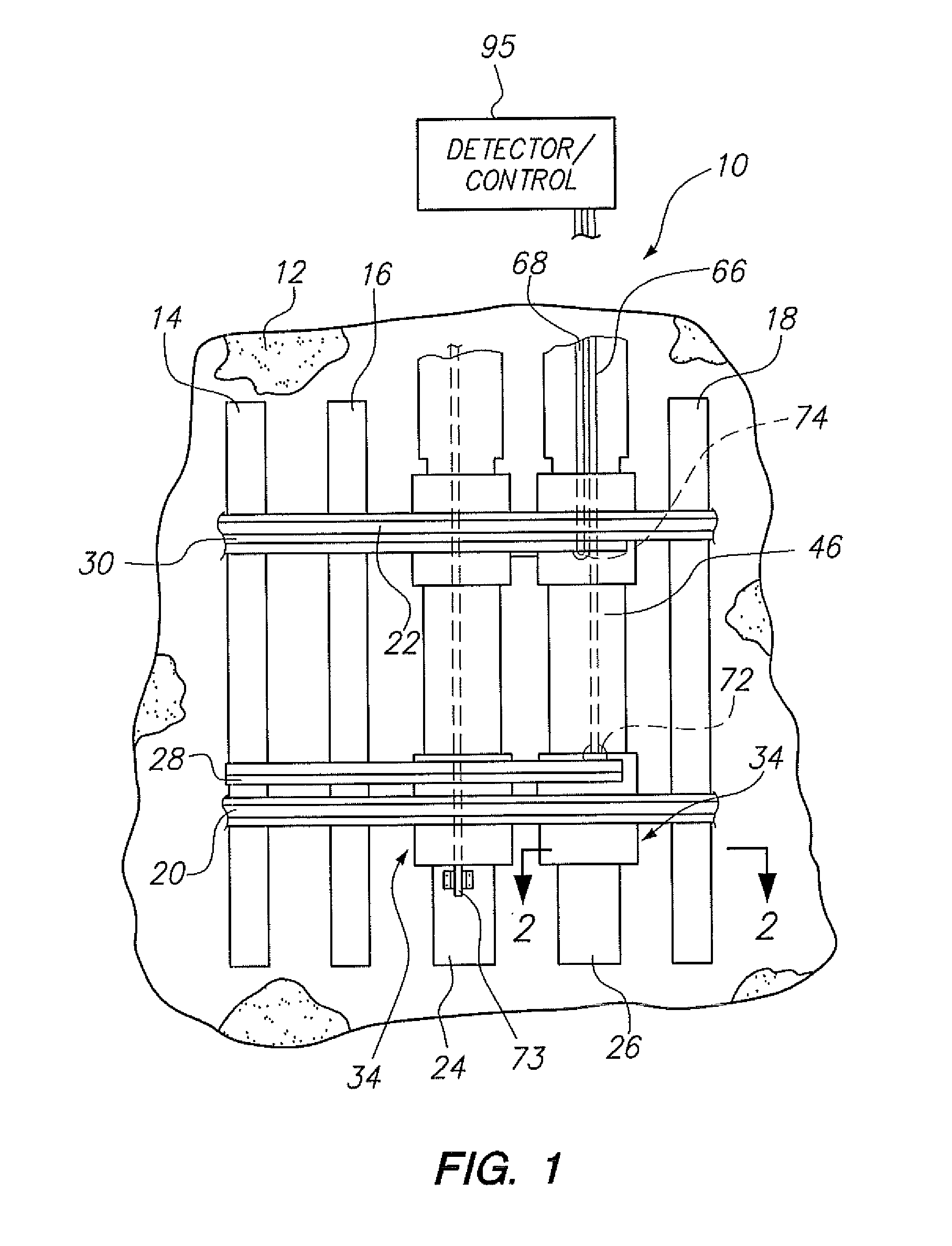
[0032]Referring now to FIG. 2, it may be observed that ...


PUM


Abstract

A railroad switching apparatus utilizing a tie which is positioned under rails and points used in switching railroad cars. A support is interposed the tie and the rails and points and includes a passageway to guide the first and second indicator bars which are attached to the points. A slider is also employed at the attachment point of the indicator bars to the points to accommodate the thermal expansion and contraction of the rails and points. The indicator bars are formed into a coaxial unit in order to allow simple observation of the relative movement between the first and second indicator bars to determine proper movement of the points relative to the rails.

Description

BACKGROUND OF THE INVENTION[0001]The present invention relates to a novel and useful railroad switching apparatus, using an over-the-tie structure.[0002]Railway switches employ moveable rails or points which are associated with moveable indicator or detector rods. Such indicator rods are normally mechanically or electronically monitored in order to determine whether or not the points have properly traveled from one position to another in the switching operation. In addition, lock rods are employed to hold the points securely in place after they have switched positions. Further, a throw rod is also employed to apply forces which effect the mechanical switching.[0003]In the past, indicator rods have been normally found adjacent to or between ties, either in a crib or on the railroad bed. Such cribs are normally located at or below the grade of the railway gravel bed. The absence of ballast around indicator rods found in such cribs provides access to the same, but the absence of ballas...

Claims


Application Information

Patent Timeline
Patent Type & Authority Applications(United States)
IPC IPC(8): E01B7/20
CPCE01B7/20B61L5/02B61L5/107E01B7/22
Inventor ARNOLD, JAMES
Owner ARNOLD JAMES
Why Eureka
Try Eureka