Check patentability & draft patents in minutes with Patsnap Eureka AI!

MEMS sensor devices having a self-test mode

a sensor device and self-testing technology, applied in the field of microelectromechanical system devices, can solve the problem of not being able to achieve straightforward dual use of terminals

Inactive Publication Date: 2017-01-05
NXP USA INC
View PDF16 Cites 4 Cited by
  • Summary
  • Abstract
  • Description
  • Claims
  • Application Information

AI Technical Summary

Benefits of technology

The patent text describes a MEMS sensor device with a self-test mode that allows for testing the sensor without using the same terminals that are used for excitation and measurement. The device uses switches to connect the sensor with a detector circuit in a cross-connection manner, which increases the sensitivity of the sensor. This allows for the testing of the sensor in a more efficient and accurate manner.

Problems solved by technology

In some sensors, such as differential acceleration sensors in which pairs of movable bodies are capable of moving in the same direction and in opposite directions, a straightforward dual use of the terminals is not possible due to the symmetry of the sensor arrangement, which typically produces no output signal when the movable bodies are moving in opposite directions during a test.

Method used


Image

  • MEMS sensor devices having a self-test mode
  • MEMS sensor devices having a self-test mode
  • MEMS sensor devices having a self-test mode

Examples


Embodiment Construction

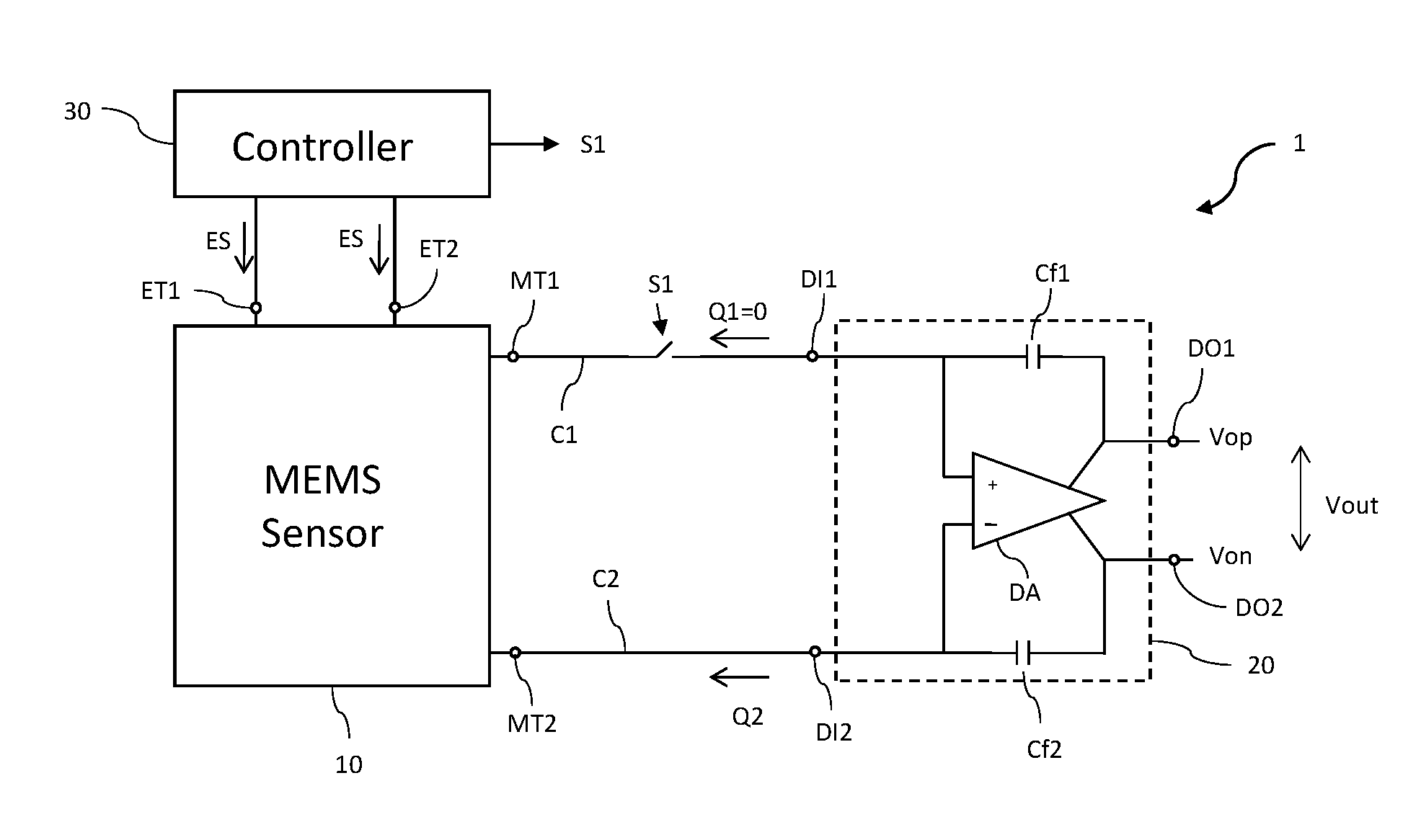
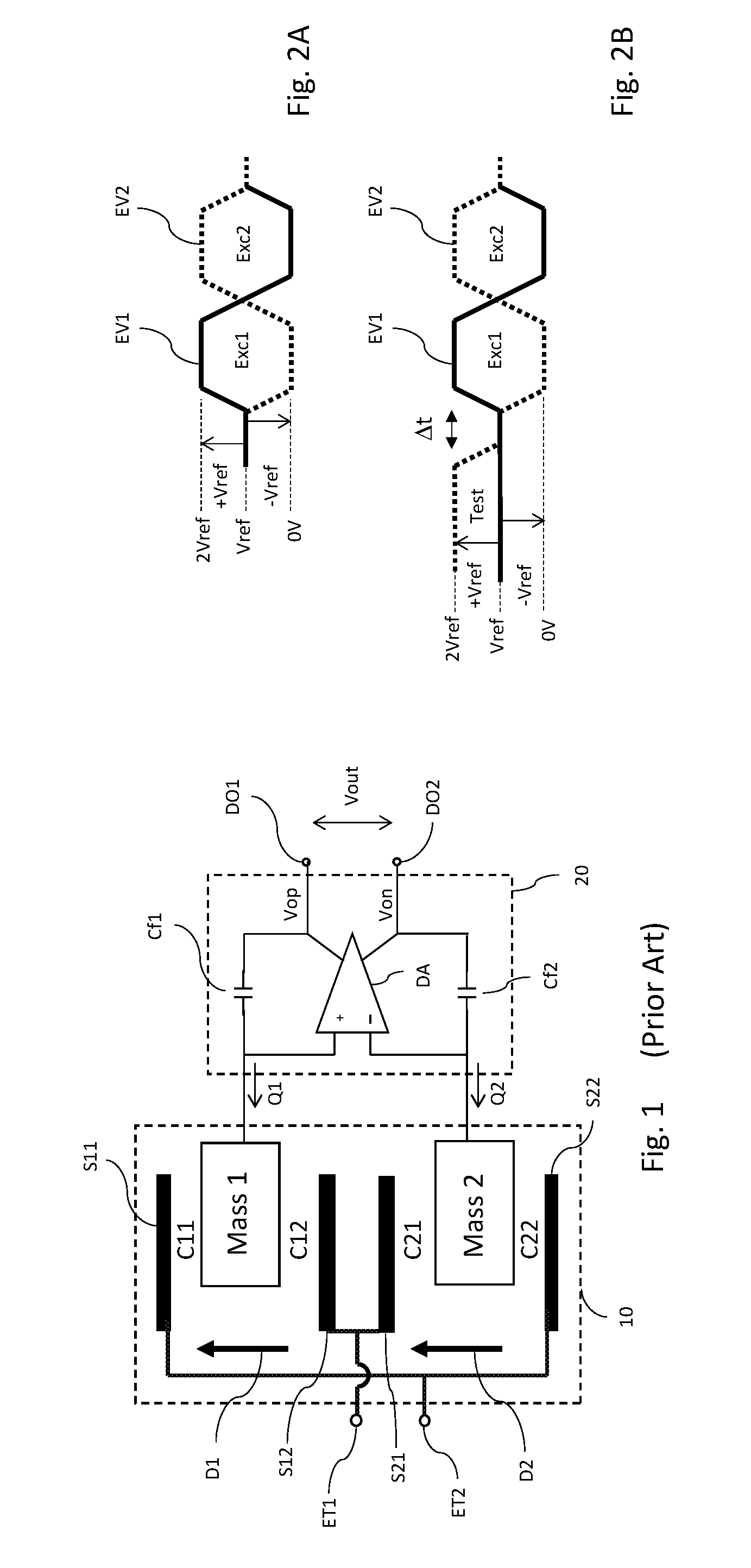
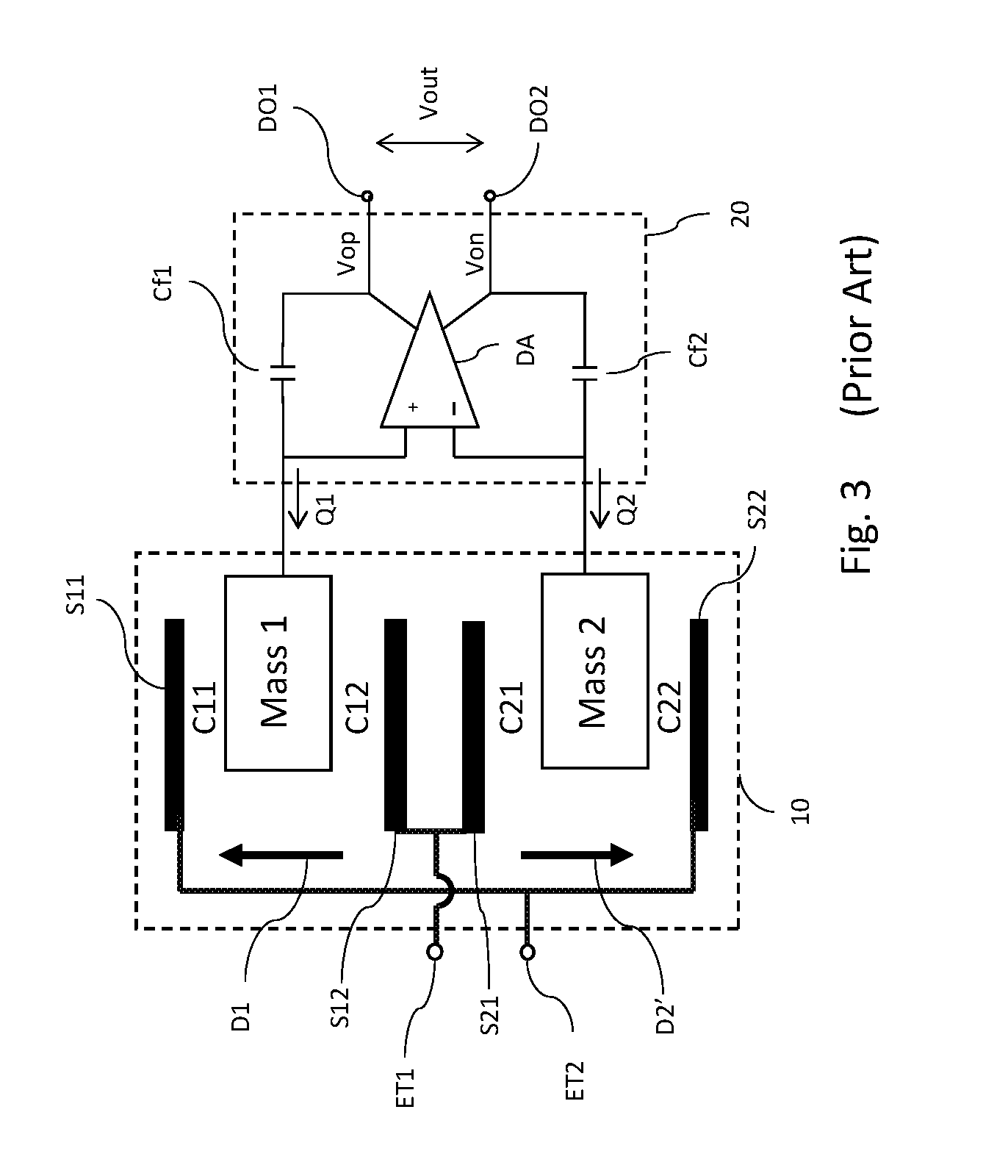
[0018]As mentioned above, the terminals of MEMS sensors may have a dual use, serving both as excitation terminals and as test terminals, but the symmetry of the sensor can prevent an output signal being produced during a test. In embodiments of the invention, dual use of the terminals of differential MEMS sensors is made possible by reading the sensor values in an asymmetric manner. To this end, in embodiments of the invention switches can be used which in a test mode connect only a single input of the detector circuit with an output of the MEMS sensor. In embodiments of the invention, at least one further switch in a cross-connection can be used to connect only a single input of the detector circuit with two outputs of the MEMS sensor, so as to increase the sensitivity of the MEMS device.

[0019]In the following, for sake of understanding, the circuitry is described in operation. However, it will be apparent that the respective elements are arranged to perform the functions being des...


PUM


Abstract

A micro-electro-mechanical system (MEMS) device comprises a micro-electro-mechanical system (MEMS) sensor; a detector circuit; a controller circuit coupled with the MEMS sensor; a first connection arranged between a first output of the MEMS sensor and a first input of the detector circuit; a second connection arranged between a second output of the MEMS sensor and a second input of the detector circuit; and a first switch arranged in the first connection. The controller circuit is configured to open the first switch during a first test mode so as to connect only a single input of the detector circuit with an output of the MEMS sensor. A further switch may be provided to connect two outputs of the MEMS sensor to a single input of the detector circuit.

Description

CROSS REFERENCE TO RELATED APPLICATION(S)[0001]The present application claims priority to International Patent Application No. PCT / IB2015 / 001341, entitled “MEMS SENSOR DEVICES HAVING A SELF-TEST MODE,” filed on Jun. 30, 2015, the entirety of which is herein incorporated by reference.DESCRIPTION[0002]Field of the invention[0003]This invention relates to micro-electro-mechanical system (MEMS) devices, such as compact MEMS accelerometer devices, which have a self-test mode.[0004]Background of the Invention[0005]MEMS devices typically include components between 1 to 100 micrometers in size (i.e. 0.001 to 0.1 mm), and generally range in size from 20 micrometers (0.02 mm) to a millimeter. A MEMS device may consist of several components that interact with the surroundings such as microsensors. Examples of such microsensors are acceleration sensors which typically include a mass which is movable, relative to a body of the device, under the influence of an acceleration. MEMS acceleration sen...

Claims


Application Information

Patent Timeline
IPC IPC(8): G01P21/00G01P15/125
CPCG01P21/00G01P15/125
Inventor ENJALBERT, JEROME ROMAINKNIFFIN, MARGARET LESLIEMCNEIL, ANDREW C.
Owner NXP USA INC
Features
  • R&D
  • Intellectual Property
  • Life Sciences
  • Materials
  • Tech Scout
  • Unparalleled Data Quality
  • Higher Quality Content
  • 60% Fewer Hallucinations
Learn More