PWM control circuit for the post-adjustment of multi-output switching power supplies

a control circuit and power supply technology, applied in the direction of ac-dc conversion, electric variable regulation, instruments, etc., to achieve the effect of simple and inexpensive circuit construction

Inactive Publication Date: 2005-04-26
STMICROELECTRONICS SRL
View PDF7 Cites 83 Cited by
  • Summary
  • Abstract
  • Description
  • Claims
  • Application Information

AI Technical Summary

Benefits of technology

[0018]An object of the present invention is to provide a PWM regulator which has a relatively simple and inexpensive circuit construction.

Problems solved by technology

More particularly, the first and second comparators may include error amplifiers.

Method used


Image

  • PWM control circuit for the post-adjustment of multi-output switching power supplies
  • PWM control circuit for the post-adjustment of multi-output switching power supplies
  • PWM control circuit for the post-adjustment of multi-output switching power supplies

Examples


Embodiment Construction

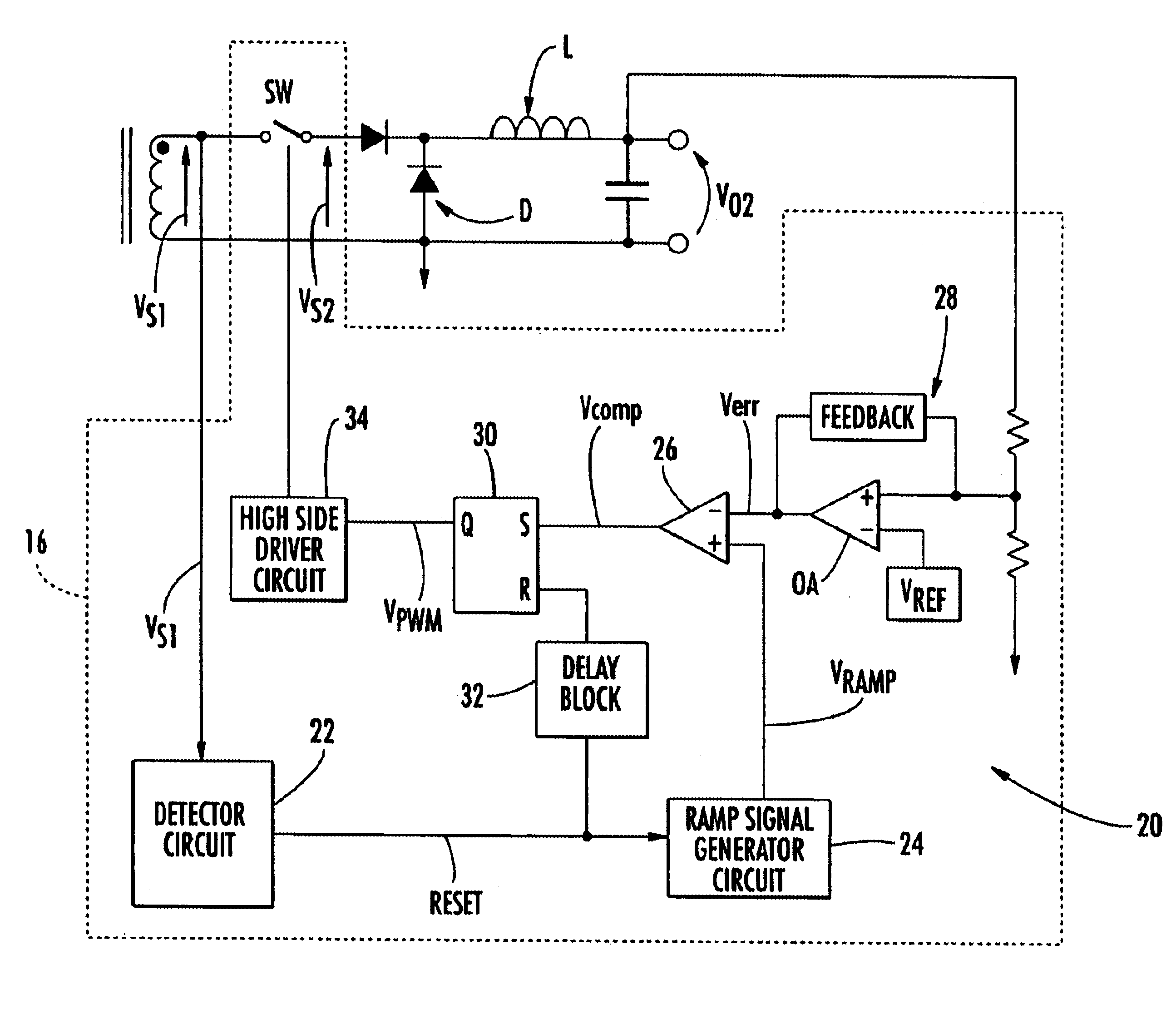
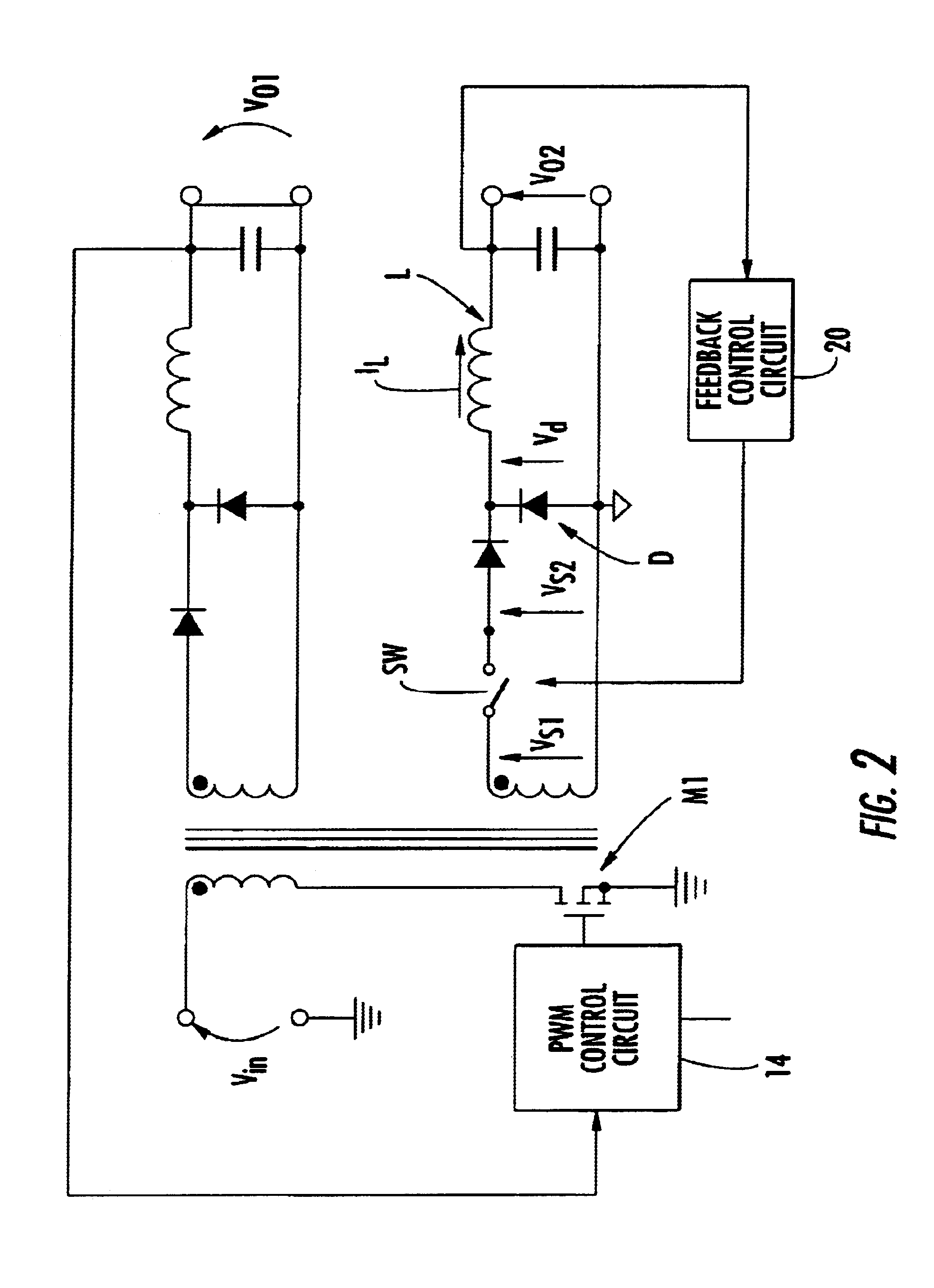
[0028]With reference to FIG. 2, a PWM cascaded regulator for multi-output power supplies in accordance with the present invention is now described. The voltage signal VS1 is established in the secondary winding of the power-supply transformer. The regulator includes an auxiliary switching device SW, and the voltage signal VS2 is downstream of the switch.

[0029]When the switch SW is made non-conductive, it blocks the propagation towards the output filter LC of the voltage signal VS1 present in the secondary transformer winding. When the switch SW is made conductive, the voltage VS1 is established almost unchanged at the terminals of the diode D.

[0030]The voltage signal Vd at the terminals of the diode D is thus a pulse width modulated waveform suitable for producing a direct current output via the filter LC. The pulse width of Vd is controlled by the duty cycle of the main switch M1 of the primary winding and by the operation of the auxiliary switch SW. The main output VO1 is regulate...


PUM


Abstract

A multi-output switching power supply may include a PWM regulator circuit arranged in cascade upstream of each output to receive, as an input, a square wave voltage signal with a predetermined duty cycle. The regulator circuit may include an auxiliary switching device for modulating the duty cycle of the input signal to supply, as an output, a regulated direct current voltage. A control circuit for the PWM regulator circuit may include a detector circuit for detecting the trailing edges of the voltage signal input to the regulator circuit which emits a pulse coinciding with each of the trailing edges. The control circuit may also include a ramp signal generator that is controlled by the emitted pulses. The ramp signal generator may be connected to the non-inverting input of a comparator having an inverting input for receiving a signal indicative of the error in the regulator output voltage.

Description

FIELD OF THE INVENTION[0001]The present invention relates to power supplies, and, more particularly, to switching power supplies having a plurality of outputs each provided with a respective pulse-width modulation (PWM) regulator and control circuits therefore.BACKGROUND OF THE INVENTION[0002]Many electronic devices require two or more isolated, stable and precisely regulated supply voltages. For example, microprocessors require a precise supply voltage of 3.3V or less, together with a conventional supply voltage of 5V. As these devices reach ever-smaller dimensions, they require increasingly higher power and higher operating efficiency. The trend of reducing component dimensions, combined with the trend of providing increasing numbers of precision supply voltages, leads to considerable difficulties in selecting suitable low cost circuits for a given purpose that can provide high energy-conversion efficiency and which have a relatively simple construction.[0003]A typical prior art s...

Claims


Application Information

Patent Timeline
Patent Type & Authority Patents(United States)
IPC IPC(8): H02M3/335H02M3/24
CPCH02M3/33561
Inventor LIBRIZZI, FABRIZIO
Owner STMICROELECTRONICS SRL
Why Eureka
Try Eureka