Dual mode flyback converter and method of operating it

Active Publication Date: 2011-06-23
STMICROELECTRONICS SRL
View PDF8 Cites 82 Cited by
  • Summary
  • Abstract
  • Description
  • Claims
  • Application Information

AI Technical Summary

Benefits of technology

[0010]A main objective is to provide an improved switching control method and implementing control circuit for a flyback DC-

Problems solved by technology

Indeed, this drawback would present itself in flyba

Method used


Image

  • Dual mode flyback converter and method of operating it
  • Dual mode flyback converter and method of operating it
  • Dual mode flyback converter and method of operating it

Examples


Embodiment Construction

[0021]Basic and preferred embodiments of the flyback converter of this disclosure will now be described in detail for better illustrating the gist of the claimed invention and the manner in which it may be practiced. The description will be made with reference to the above listed figures though it is understood that alternative schemes may be devised for practicing the novel technique of this disclosure, on the basis of design preferences and / or requirements of the specific application. Therefore the invention is not intended to be limited to the exemplary embodiments described and illustrated herein.

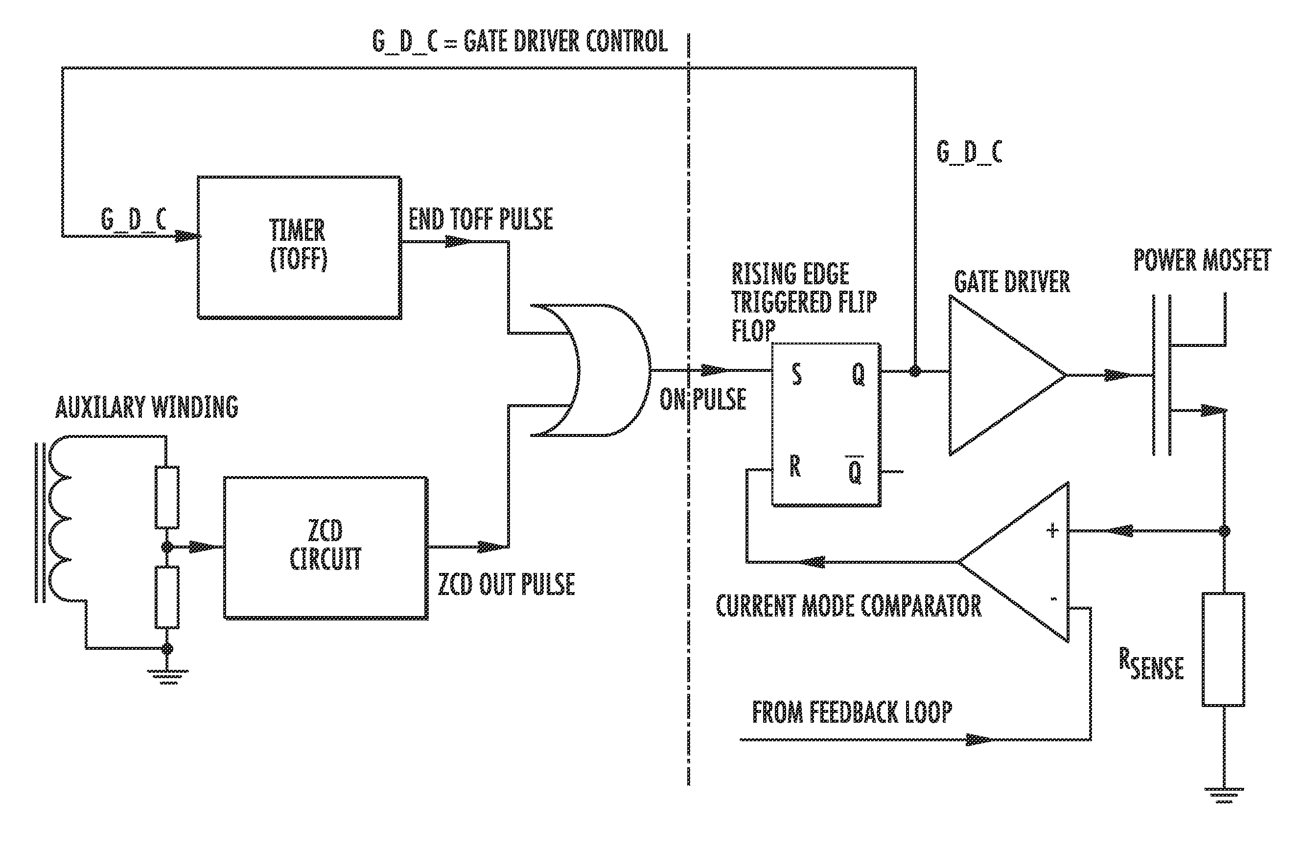
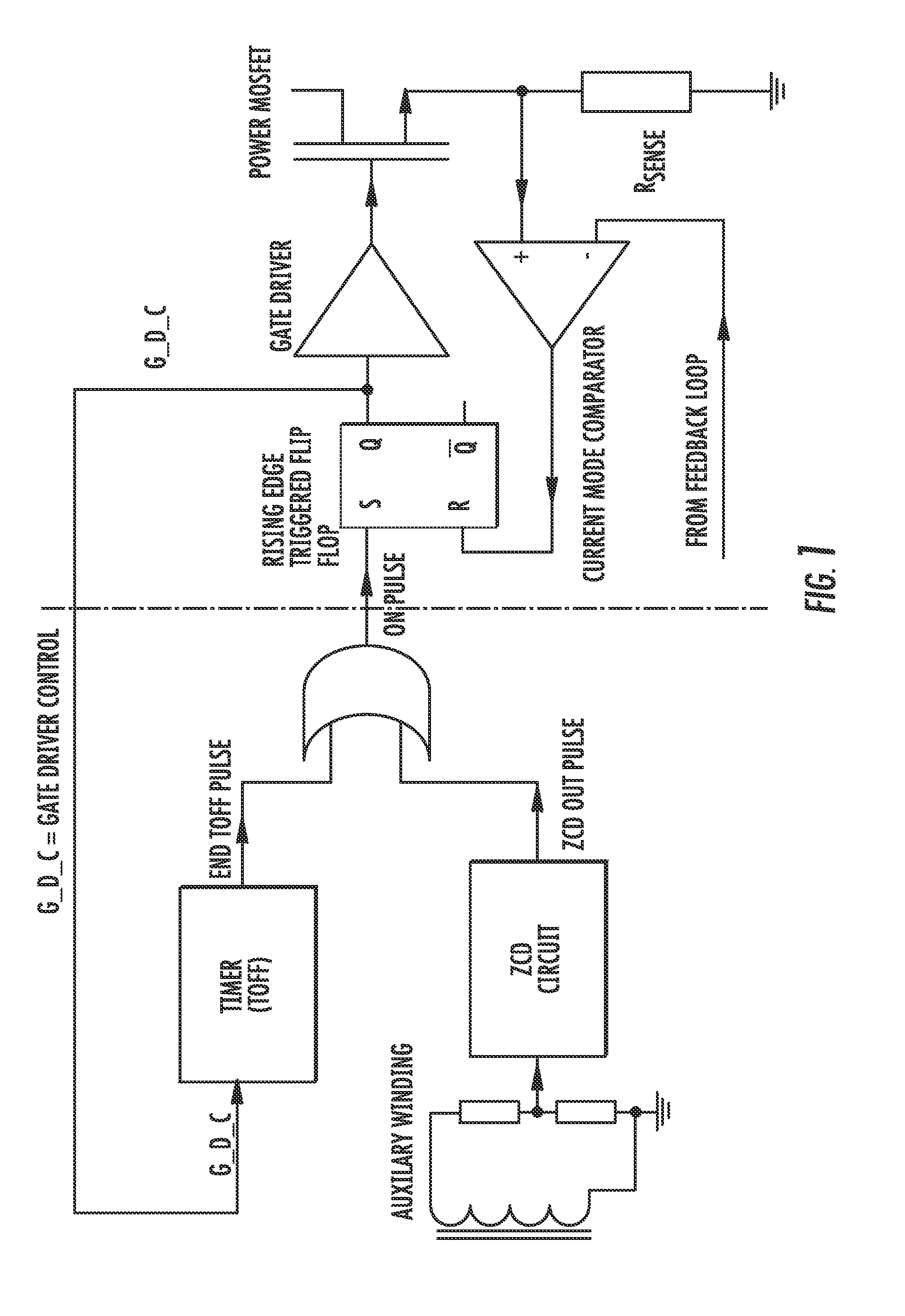
[0022]A common way of controlling a flyback converter that will allow operation in a continuous conduction mode is the so-called fixed frequency mode, wherein an oscillator waveform within the controller decides the instant of switching on of the power switch.

[0023]A potential drawback is that in case a current mode control is implemented, according to which the switching off of the pow...


PUM

PropertyMeasurementUnit
Currentaaaaaaaaaa
Electric potential / voltageaaaaaaaaaa
Frequencyaaaaaaaaaa

Abstract

A DC-DC converter includes a power switching device and a mode control logic circuit to control the power switching device and generate an ON-pulse. A flip-flop is configured to be set by the mode control logic circuit. A current mode comparator is configured to reset the flip-flop and to compare a signal based upon current flowing through the power switching device with a signal based upon an output voltage of the dual mode flyback DC-DC converter. A transformer is driven by the current mode comparator. The mode control logic circuit includes a timer starting when a gate driver control signal applied to the power switching device turns the power switching device off and configured to generate a pulse when an off time interval elapses, a zero current detector circuit configured to sense a voltage on the transformer and generate a pulse when the voltage drops below a trigger threshold, and a combinatory logic circuit configured to compare pulse signals generated by the timer and the zero current detector circuit and generate the ON-pulse based thereupon.

Description

FIELD OF THE INVENTION[0001]This invention relates, generally, to switching power supplies for electronic devices, and, more in particular, to the control circuit of a flyback DC-DC converter and a method of operating the converter.BACKGROUND OF THE INVENTION[0002]Regulated power supplies are used in electronic devices and apparatuses. The core of so called switching power supplies that offer a more efficient conversion than classical linear transformer-based power supplies is a switched DC-DC converter. Switched DC-DC converters may be realized with one of many circuital topologies, the choice of which may be dictated by design considerations, convenience or specific requirements.[0003]Generally, hard switching converter topologies give rise to transient signals, the spectrum of which contains high frequency components that may have effects of electromagnetic emissions, introducing noise in the area surrounding the converter circuit. The noise may interfere with information carryin...

Claims


Application Information

Patent Timeline
IPC IPC(8): H02M3/335H01F7/06
CPCH02M3/33507Y02B70/1433Y10T29/4902Y02B70/10
Inventor STRACQUADAINI, ROSARIO
Owner STMICROELECTRONICS SRL
Why Eureka
Try Eureka