
Gaze tracking device and a head mounted device embedding said gaze tracking device

a tracking device and head mounted technology, applied in the field of gaze tracking devices, can solve the problems of limited field of view, difficult embedding of bulgy gaze tracking devices in hmd,

Inactive Publication Date: 2017-01-05
INTERDIGITAL CE PATENT HLDG
View PDF11 Cites 14 Cited by
  • Summary
  • Abstract
  • Description
  • Claims
  • Application Information

AI Technical Summary

Benefits of technology

This patent describes a device that tracks a user's eye movements to control a computer or other device in a system. The device uses infra-red light that is projected onto the eye and captured by a camera. By analyzing the captured light, the device can detect the user's gaze and move the computer or device accordingly. The device can be embedded in a head mounted device or a computer program that can be executed on a computer or programmable device. The technical effects include improved efficiency and accuracy in eye movement tracking for control of computers and other devices.

Problems solved by technology

This results in bulky gaze tracking devices difficult to embed in a HMD.
Another limitation of this method is the field of view which is limited due to the illumination scheme combined with the geometry of the reflected images.

Method used


Image

  • Gaze tracking device and a head mounted device embedding said gaze tracking device
  • Gaze tracking device and a head mounted device embedding said gaze tracking device
  • Gaze tracking device and a head mounted device embedding said gaze tracking device

Examples


first embodiment

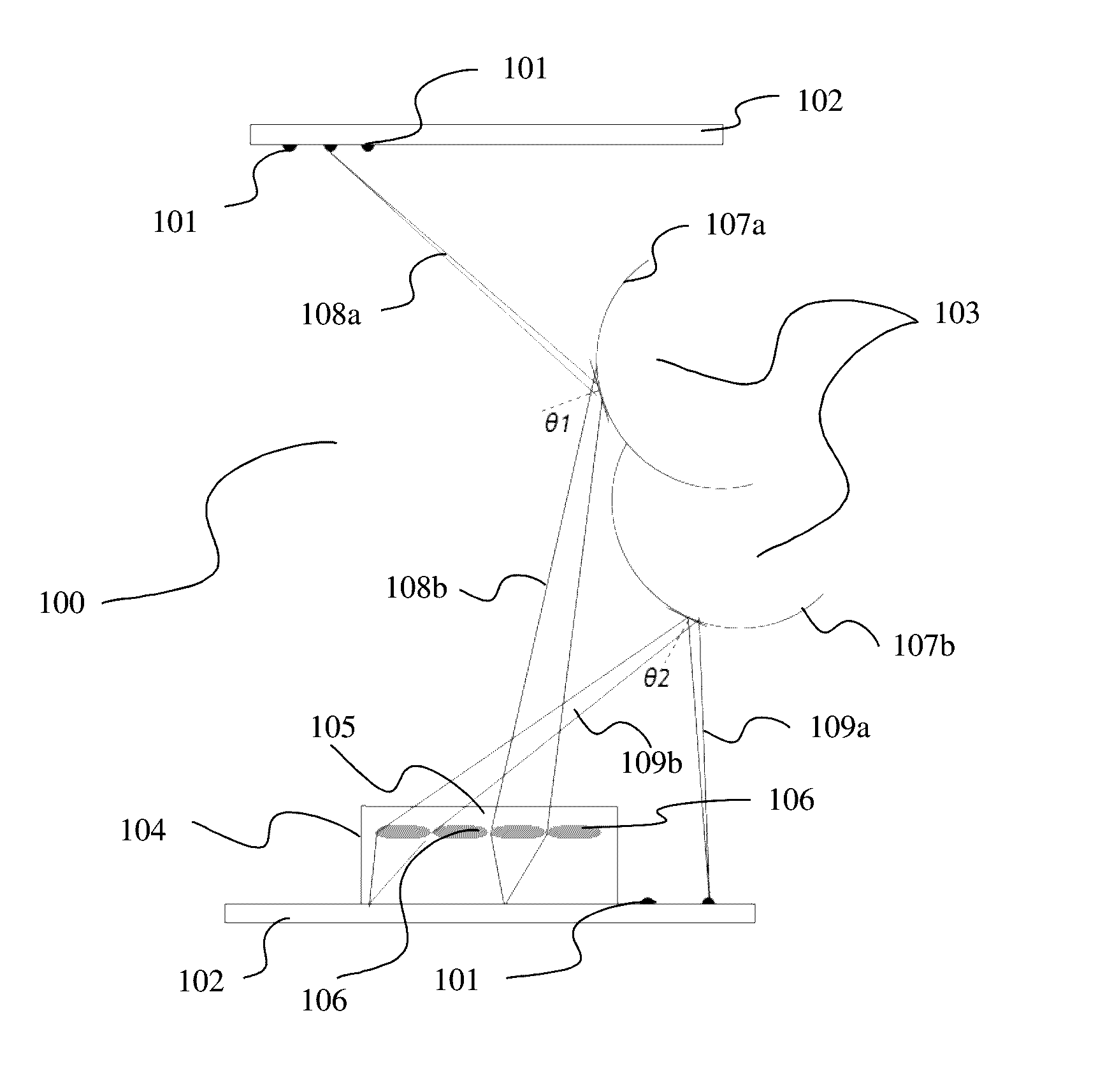
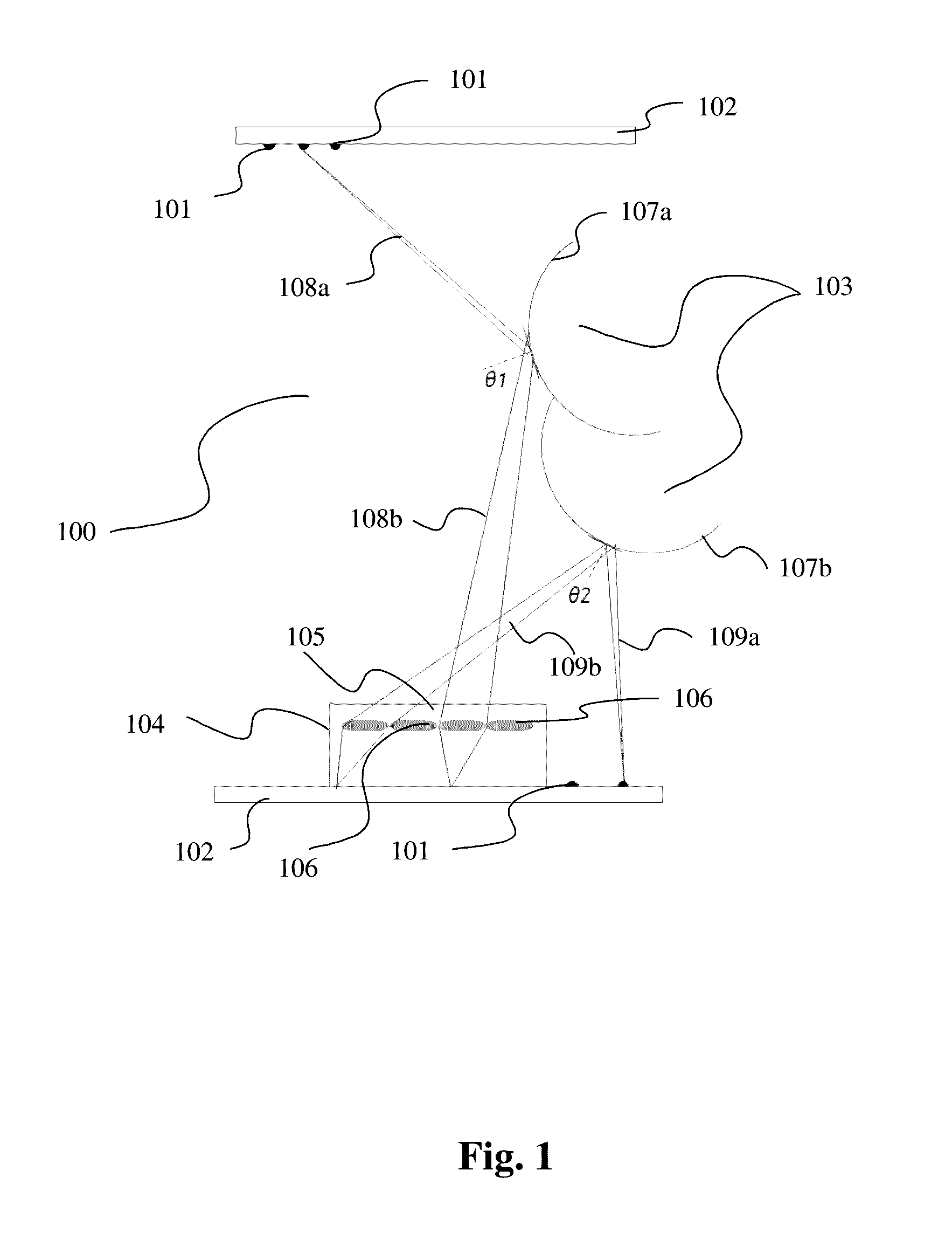
[0035]In the invention, the IR light sources 101 emit a polarized IR light. The polarization of the IR light may be achieved by equipping the IR light sources 101 with polarizing filters.

second embodiment

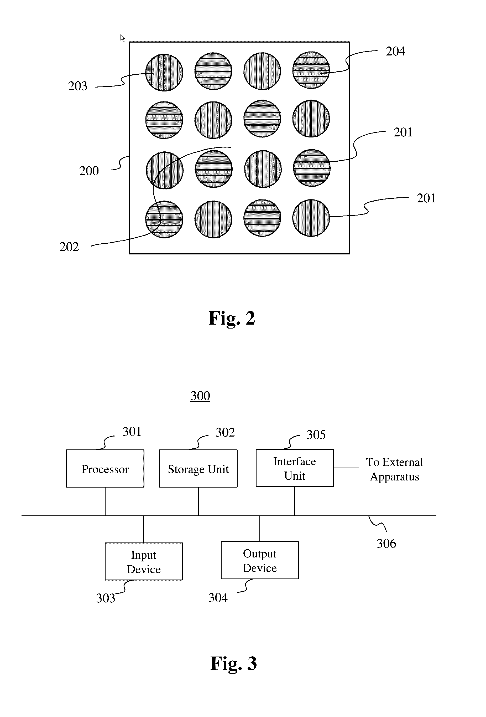
[0036]In the invention represented on FIG. 2, the micro-lenses 201 of the micro-lens array 202 of the light-field camera 200 are equipped with polarizing filters. For example the micro-lenses 201 are equipped with two different types of polarizing filters 203, 204. For example, the polarizing filters 203, 204 may be of the linear polarization type, the polarizations of the polarizing filters 203, 204 being orthogonal to each other. The polarizing filters 203, 204 may also be of the circular polarization type, the polarizations of the polarizing filters 203, 204 being in reverse sense to each other.

[0037]The reflection on the surface of the eyeball of a non-polarized IR light emitted by the IR light sources 101 may provide a natural polarization. Indeed when the incidence angle of the emitted IR light is targeted to be equal to the Brewster angle, the polarization of the reflected IR light is close to a parallel polarization, i.e. the polarization of the reflected IR light is orthogo...

third embodiment

[0058]The reflection on the surface of the eyeball of a non-polarized IR light emitted by the IR light sources 101 may provide a natural polarization. Thus in the head mounted device 400, some of the IR light sources 402a, 402b emit a polarized IR light while other IR light sources 402a, 402b emit a non-polarized IR light. The IR light sources emitting a non-polarized IR light are selected based on the incidence angle of the IR light emitted and the knowledge that depending on this incidence angle the reflection of the incident IR light on the eyeball results in a natural polarization of the reflected IR light.

[0059]In another embodiment of the head mounted device 400, the selection of the IR light sources 402a, 402b emitting a polarized IR light is dynamic and is based on the current position of the eye of the user. Thus, depending on the current position of the eye of the user, a given IR light source 402a, 402b emits or does not emit a polarized IR light.

[0060]In order to determi...


PUM


Abstract

The present disclosure generally relates to a gaze tracking device. Gaze tracking is a process of measuring either the point of regard or the motion of an eye relatively to the head of a person. A gaze tracking device is a device capable of measuring eye positions and eye movement. In order to track the gaze of a person, infra-red light is projected into the user's eye. Utilizing the primary Purkinje reflection and the pupil-masked reflection, the position of the eye of the user is determined. The gaze tracking devices running such a tracking method offer a limited field of view due to the illumination scheme combined with the geometry of the reflected images. It is proposed a gaze tracking device embedding a light-field camera. Such a gaze tracking device may be embedded in a head mounted device.

Description

TECHNICAL FIELD[0001]The present disclosure generally relates to a gaze tracking device capable of providing a reliable and accurate tracking of the gaze of a user, among others for users with narrow eye opening.BACKGROUND[0002]Gaze tracking is a process of measuring either the point of regard or the motion of an eye relatively to the head of a person. A gaze tracking device is a device capable of measuring eye positions and eye movement.[0003]As disclosed in patent application WO 2013 / 167864, gaze tracking is a key feature of Head Mounted Devices or HMD for it can extend the ability of a user of such a HMD to gaze at an object located beyond the head mobility limits. One gaze tracking technology consists in projecting infra-red light into the user's eye and utilizing the primary Purkinje reflection and the pupil-masked reflection in order to determine the position of the eye of the user of the HMD. This method consists in tracking a relative motion of reflected images in order to e...

Claims


Application Information

Patent Timeline
IPC IPC(8): G06K9/00H04N5/33G02B27/01
CPCG02B27/0093G02B27/0179G02B2027/0187H04N23/20A61B3/113G06F3/013G02B2027/0138G02B27/0172G02B5/30G02B27/017G02B27/0075H04N23/957H04N23/81G06V40/19G02B27/0176H04N5/33
Inventor DORE, RENAUDGALPIN, FRANCKVANDAME, BENOIT
Owner INTERDIGITAL CE PATENT HLDG
Learn More