Three-dimensional flow field test method based on double-light-field camera

A technology of three-dimensional flow field and test method, which is applied in fluid velocity measurement, measurement device, velocity/acceleration/impact measurement, etc., can solve the problems of large installation space, cumbersomeness, and complicated calibration process of cameras, so as to reduce the hardware system configuration, Improves precision and accuracy, simplifies the effect of adjustment steps

Inactive Publication Date: 2018-01-09
SHANGHAI JIAO TONG UNIV
View PDF7 Cites 20 Cited by
  • Summary
  • Abstract
  • Description
  • Claims
  • Application Information

AI Technical Summary

Problems solved by technology

The calibration process of multiple camera space coordinates is complex and cumbersome, and multiple cameras require a large installation space
Document 2 (Brian S Thurow "Volumetric particle image velocimetry with a single plenoptic camera" Measurement Science and Technology 26 (2015) pp.25-28) and Document 3 (Junfei Ding, Jianhua Wang and ShengxianShi (2015) Dense ray tracing based reconstruction algorithm for light fieldvolumetric particle image velocimetry. The 7th Australian Conference on LaserDiagnostics in Fluid Mechanics and Combustion, Melbourne, Australia) used a single camera. Due to the small viewing angle of a single camera, the reconstructed particles have obvious elongation effect, along the main axis of the camera The velocity vector error in the depth direction is large

Method used


Image

  • Three-dimensional flow field test method based on double-light-field camera
  • Three-dimensional flow field test method based on double-light-field camera
  • Three-dimensional flow field test method based on double-light-field camera

Examples


Embodiment Construction

[0062] The present invention will be described in detail below in conjunction with specific embodiments. The following examples will help those skilled in the art to further understand the present invention, but do not limit the present invention in any form. It should be noted that those skilled in the art can make several changes and improvements without departing from the concept of the present invention. These all belong to the protection scope of the present invention.

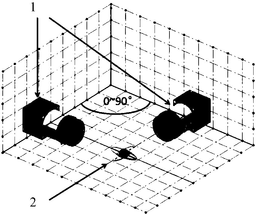
[0063] figure 1 In the middle, 1 is two light field cameras arranged at a certain angle, and 2 is a schematic diagram of reconstructed tracer particles; the two light field cameras are arranged at a certain angle, so as to eliminate the elongation effect of reconstructed particles.

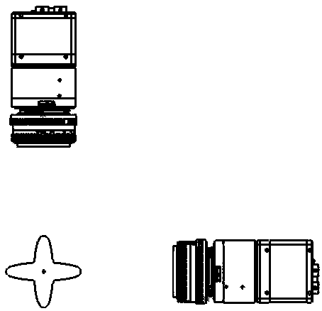
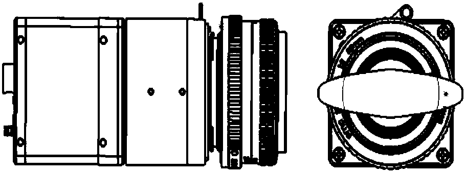
[0064] figure 2 and image 3 It is a schematic diagram of different viewing angles of the dual camera system.

[0065] Figure 4 In the middle, 3 is the main lens, 4 is the microlens array, and 5 is the CCD / CMOS sensor...


PUM


Abstract

The invention provides a three-dimensional flow field test method based on a double-light-field camera. The method comprises the following steps: obtaining time sequence particle light-field images oftrace particles in a flow field to be measured through the double-light-field camera; carrying out pretreatment on the time sequence particle light-field images to remove background noise; carrying out reconstruction on the time sequence particle light-field images through a GPU parallel processing method to obtain a time sequence three-dimensional particle image; carrying out cross correlation calculation on the time sequence three-dimensional particle image through a fast Fourier transform method to obtain three-dimensional flow field velocity field distribution; and carrying out postprocessing on the three-dimensional flow field velocity field to reject error velocity vectors, and meanwhile, replacing the rejected error vectors with adjacent correct vector interpolation. Compared withan existing single-light-field three-dimensional flow field test method, the method eliminates the elongation effect of the reconstructed particles in the direction of the optical axis, and greatly improves velocity vector precision and accuracy; and meanwhile, compared with a conventional multi-visual-angle three-dimensional flow field test method, the method greatly reduces hardware system configuration and simplifies hardware system adjustment steps, and is especially suitable for three-dimensional flow field measurement under a restricted space.

Description

technical field [0001] The invention belongs to the technical field of flow field observation, and in particular relates to a three-dimensional flow field testing method based on a dual light field camera. Background technique [0002] In the prior art, document 1 (Scarano F "Tomographic PIV: principles and practice" Measurement Science and Technology 24 (2013) pp.1-28) in order to measure the three-dimensional velocity of the fluid, adopts a tomography composed of more than four cameras Particle imaging system. The process of calibrating the space coordinates of multiple cameras is complex and cumbersome, and multiple cameras require a large installation space. Document 2 (Brian S Thurow "Volumetric particle image velocimetry with a single plenoptic camera" Measurement Science and Technology 26 (2015) pp.25-28) and Document 3 (Junfei Ding, Jianhua Wang and ShengxianShi (2015) Dense ray tracing based reconstruction algorithm for light fieldvolumetric particle image velocim...

Claims


Application Information

Patent Timeline
Patent Type & Authority Applications(China)
IPC IPC(8): G01P5/22
Inventor 施圣贤梅迪
Owner SHANGHAI JIAO TONG UNIV
Why Eureka
Try Eureka