
Space ring and lens

A spacer and lens technology, used in installation, optics, instruments, etc., can solve glare, serious problems, etc., to reduce glare, reduce reflectivity, and ensure assembly accuracy.

Inactive Publication Date: 2021-11-16
ZHEJIANG SUNNY OPTICAL CO LTD
View PDF5 Cites 0 Cited by
  • Summary
  • Abstract
  • Description
  • Claims
  • Application Information

AI Technical Summary

Problems solved by technology

However, the smaller the light-transmitting part, the larger the mounting part needs to be supported. Although the larger mounting part is helpful for the stability of the lens assembly, it will also make the glare more serious

Method used


Image

  • Space ring and lens
  • Space ring and lens
  • Space ring and lens

Examples


Embodiment Construction

[0033] In order to more clearly describe the embodiments of the present invention or the technical solutions in the prior art, the following will briefly introduce the drawings that are used in the embodiments. Apparently, the drawings in the following description are only some embodiments of the present invention, and those skilled in the art can also obtain other drawings according to these drawings without creative efforts.

[0034] When describing the embodiments of the present invention, the terms "vertical", "transverse", "upper", "lower", "front", "rear", "left", "right", "vertical", " The orientation or positional relationship expressed by "horizontal", "top", "bottom", "inner" and "outer" is based on the orientation or positional relationship shown in the relevant drawings, which are only for the convenience of describing the present invention and simplifying the description, and It is not to indicate or imply that the device or element referred to must have a particu...


PUM


Abstract

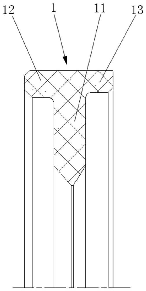
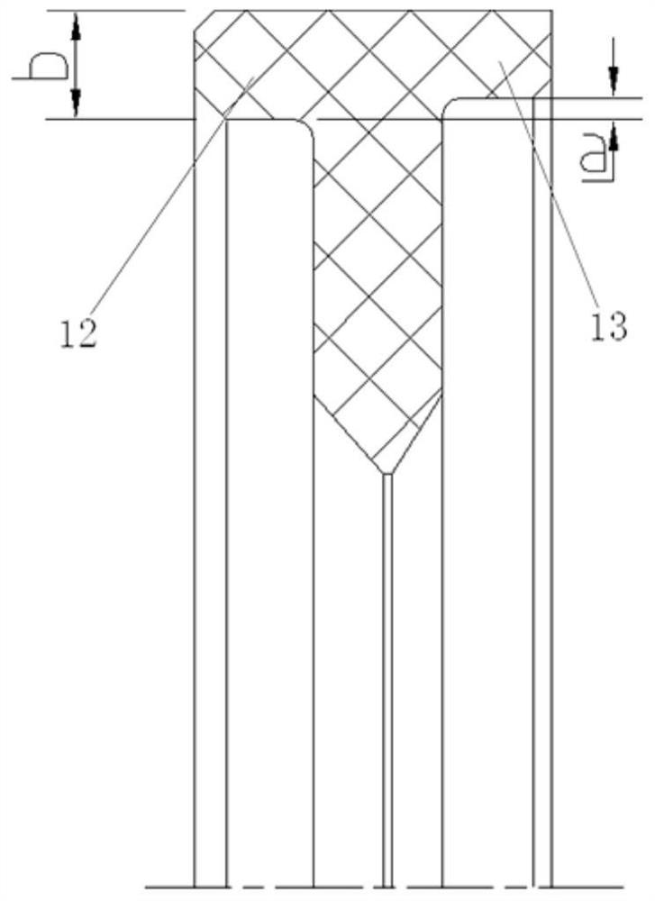
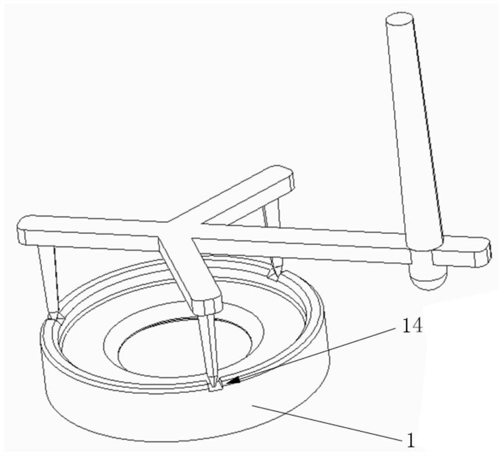
The invention relates to a space ring (1) and a lens. The space ring (1) comprises an annular body (11), and the outer side of the annular body (11) separately extends towards an object side and an image side along an optical axis to form a first bearing part (12) and a second bearing part (13). With the space ring of the invention adopted, the assembly stability of the lens can be remarkably improved, and dazzle light can be effectively weakened.

Description

technical field [0001] The invention relates to the technical field of optical elements, in particular to a spacer and a lens. Background technique [0002] With the continuous improvement of consumers' requirements for mobile phone photography, wide-field and large-format imaging effects are becoming more and more important, and wide-angle lenses can perfectly meet the above requirements. Therefore, wide-angle lenses have made great progress, and their field of view has evolved from 85° to more than 120°. However, as the field of view increases, the chromatic aberration of the lens becomes more and more difficult to control. It is necessary to design a central diaphragm to effectively control the optical chromatic aberration. For this lens structure, when the light passes through the lens structure with a central diaphragm, the path the light passes through is basically a "V" shape after being refracted by the lens group, which means that the lens in the middle of the lens...

Claims


Application Information

Patent Timeline
Patent Type & Authority Applications(China)
IPC IPC(8): G02B5/00G02B7/02
CPCG02B5/005G02B5/003G02B7/021
Inventor 常斌全戴付建赵烈烽
Owner ZHEJIANG SUNNY OPTICAL CO LTD
Learn More