Calibration method for microlens light field camera

A light field camera and calibration method technology, which is applied in image data processing, instruments, calculations, etc., to achieve accurate calibration results, comprehensive functions, and improve calibration efficiency

Active Publication Date: 2018-11-09
南通爱邦智能科技有限公司
View PDF4 Cites 20 Cited by
  • Summary
  • Abstract
  • Description
  • Claims
  • Application Information

AI Technical Summary

Problems solved by technology

In these methods of calibrating internal and external parameters, the simplicity, computational efficiency, and accuracy of the calibration scheme need to be further improved.

Method used


Image

  • Calibration method for microlens light field camera
  • Calibration method for microlens light field camera
  • Calibration method for microlens light field camera

Examples


Embodiment Construction

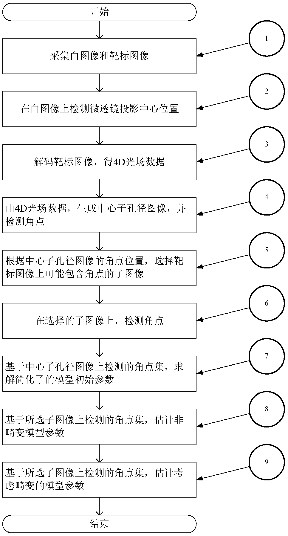
[0041] The present invention will be further described below in conjunction with accompanying drawing.

[0042] Such as figure 1 Shown, the present invention comprises the following steps:

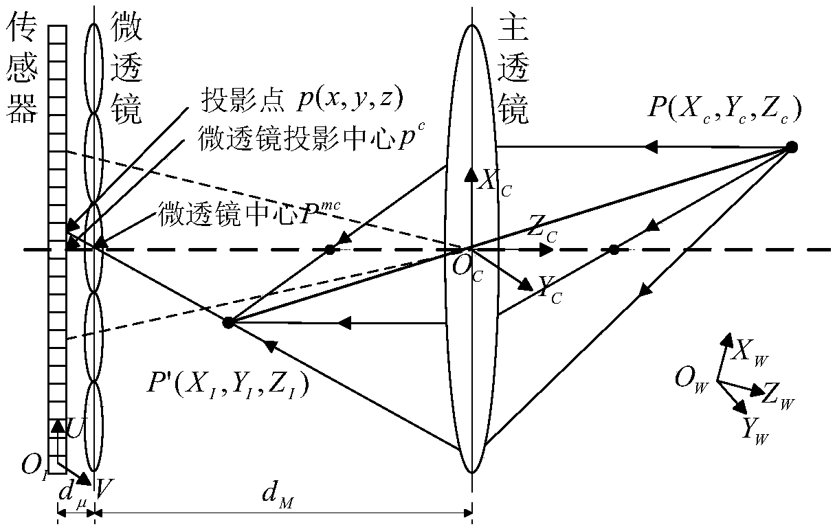
[0043] Step 1, use a microlens light field camera plenoptic 1.0 to capture a high-exposure original white image and checkerboard target raw image The optical path model of the microlens light field camera is as follows figure 2 As shown, let the distance between the microlens array and the sensor be d μ , the distance between the main lens and the main lens is d M , the focal length of the main lens is F. Take the optical center and optical axis of the main lens as the camera coordinate system (O C -X C Y C Z C ) coordinate origin and Z C Axis, the direction pointing to the scene is Z C The positive direction of the axis, X C , Y C axis direction see figure 2 . The light emitted by the scene point P converges at P’ through the main lens, and then passes through the cente...


PUM


Abstract

The invention discloses a calibration method for a microlens light field camera. The method comprises steps: based on the microlens light field camera, a white image and a target image are acquired; the microlens projection center position is detected on the white image; according to the microlens projection center position, the target image is decoded to obtain 4D light field data; a center sub-aperture image is generated by the 4D light field data, and corner points are detected; according to the corner point positions detected on the center sub-aperture image, sub images possibly containingthe corner points on the target image are selected; on the selected sub images, the corner points are detected; based on a corner point set detected on the center sub-aperture image, simplified modelinitial parameters are solved; based on a corner point set detected on the selected sub images, non-distorted model parameters are estimated; and with the non-distorted model parameters as initial values and based on the corner point set detected on the selected sub images, model parameters considering distortion are further estimated. The calibration method can estimate inner and outer parameters of the light field camera at the same time, functions are comprehensive, the result is accurate, and the efficiency is high.

Description

technical field [0001] The invention relates to the fields of computer vision, computational photography and light field image processing, in particular to a calibration method for a microlens light field camera. Background technique [0002] The hand-held light field camera designed by R.Ng et al. in 2005 has become a representative of microlens array light field acquisition equipment, which directly promoted the rapid entry of light field cameras (such as Lytro, Raytrix, etc.) into the civilian market. It set off an upsurge of applied research on light field imaging. For example: digital refocusing based on light field data achieves the effect of taking pictures first and then focusing; using different viewpoints to synthesize images to achieve 3D visual effects. Typical applications include alpha extinction, saliency detection, depth estimation, super-resolution, etc. In the field of robotics, light-field cameras composed of camera arrays have been successfully used in ...

Claims


Application Information

Patent Timeline
Patent Type & Authority Applications(China)
IPC IPC(8): G06T7/80
CPCG06T2207/10052G06T7/80
Inventor 韩磊刘黄骁烈夏明亮吕俊斌徐梦溪郑胜男张建德黄陈蓉
Owner 南通爱邦智能科技有限公司
Why Eureka
Try Eureka