System for complete dispensing of flowable materials from a bulk shipping container

a technology for flowable materials and bulk shipping containers, which is applied in the field of complete dispensing of flowable materials contained in bulk shipping containers, can solve the problems of increasing the residual product left in the plastic bag, affecting the quality of the product, and affecting the disposal of users, so as to achieve the effect of increasing the number of products, increasing the quality of plastic materials, and increasing the flexibility of product offerings

Active Publication Date: 2017-01-12
INT PAPER CO
View PDF11 Cites 8 Cited by
  • Summary
  • Abstract
  • Description
  • Claims
  • Application Information

AI Technical Summary

Benefits of technology

[0009]The present invention is directed to a system or an apparatus and method for complete dispensing of bulk material from a product bag disposed in a bulk bin or tote. The product bag is a three ply plastic bag and the air inflated bag is a two ply plastic bag. However, one of ordinary skill in the art would appreciate that each of the product bag and the air inflated bag may be one, two, three, four plies or any combination thereof. One advantage of the respective product bag and air inflated bag is their higher quality plastic material, but yet the total cost of the respective plastic bags is significantly less than the prior art bags. Furthermore, the ability to glue tape an air inflated bag to any stock product bag provides much greater flexibility in our product offerings without increased inventory.
[0010]Accordingly, one aspect of the present invention is directed to a system for fully dispensing flowable bulk material from a bulk shipping container. The system comprises a tote or a bulk bin having a dispensing opening. A first flexible bag is disposed inside the bulk bin. The first flexible bag includes an inlet port for receiving the flowable bulk material and an outlet port for dispensing the flowable bulk material from the first flexible bag. The outlet port of the first flexible bag is inserted into the dispensing opening. A second flexible bag is removably attached to the first flexible bag. The second flexible bag includes an air inlet port that is formed at one end thereof and is used for inflating the second flexible bag from a source of pressurized air. The second flexible bag further includes an obstruction region defined by a weld line that is formed on an opposite end from the air inlet port to redirect the pressurized air within the second flexible bag. When inflating the second flexible bag reaches a level at which the pressurized air counteract the flowable material pressure within the first flexible bag so as to urge the flowable bulk material toward the outlet port of the first flexible bag.

Problems solved by technology

Bulk material shipping containers often contain products that are viscous or sticky, thus the products don't flow easily or they adhere to the plastic bag when being dispensed.
The result is more residual product left in the plastic bag which becomes expensive waste and a disposal issue for the users.
These two design approaches incur high cost and complexity and the bag that is used is a three ply bag that has a series of welds between the outer and middle ply that allow air to be inserted between the outer and middle ply in a way so as to force the product inside of the bag to the outlet point.
These bags are expensive to make as there are two bags to be made and an off-line process to weld the two plastic bags together.
The aforementioned prior art bags' performances are comparable to one another, but not significantly better or worse.

Method used


Image

  • System for complete dispensing of flowable materials from a bulk shipping container
  • System for complete dispensing of flowable materials from a bulk shipping container
  • System for complete dispensing of flowable materials from a bulk shipping container

Examples


Embodiment Construction

[0027]While this invention is susceptible of embodiment in many different forms, there is shown, in the drawings, several specific embodiments with the understanding that the present disclosure is to be considered as an exemplification of the principles of the invention and is not intended to limit the invention to the embodiments illustrated. It will be understood that like or analogous elements and / or components, referred to herein, are identified throughout the drawings by like reference characters. In addition, it will be understood that the drawings are merely representations of the present invention, and some of the components may have been distorted from actual scale for purposes of pictorial clarity.

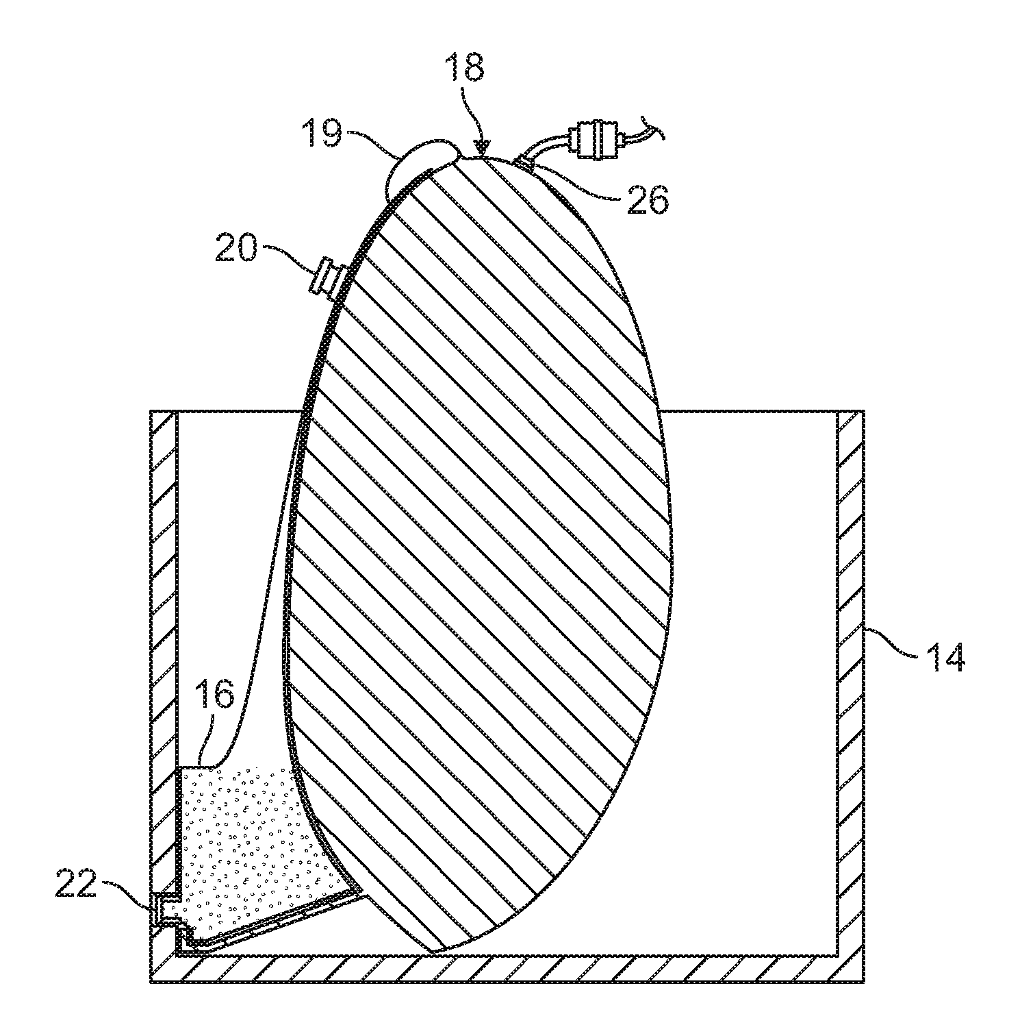
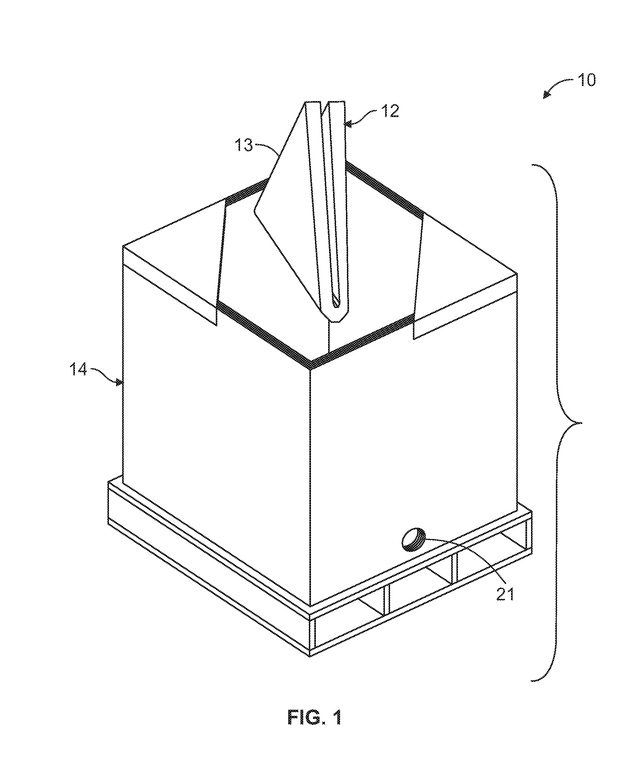
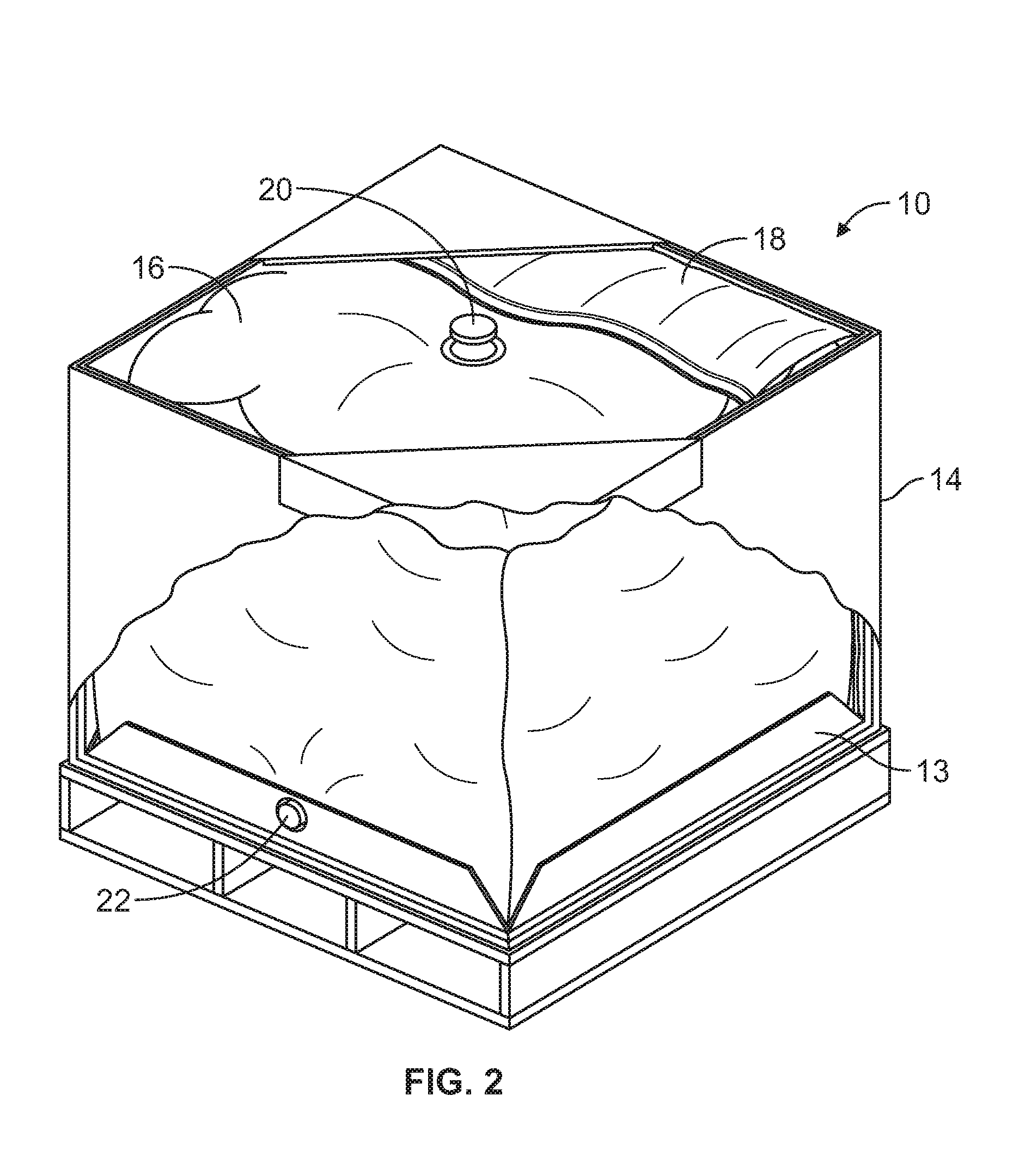
[0028]FIG. 1 is a top perspective view of an intermediate bulk container (IBC) 10 having an assembled bin or tote 14 and a cassette 12 positioned in a space relationship with the tote or bin. The cassette 12 is defined by a foldable cassette board 13 that contains a first flexibl...


PUM


Abstract

The present invention is directed to a system for fully dispensing liquid from a bulk shipping container. The system includes a bulk bin and a cassette disposed therein. The cassette includes a cassette board, a liquid bag having inlet and outlet ports and an air inflated bag that is attached to the liquid bag. The air bag includes an air inlet port formed at one end thereof and used for inflating the air bag from a source of pressurized air. The air bag further includes an obstruction region defined by a weld line that is formed on an opposite end from the air inlet port to redirect the pressurized air within the air bag when inflating the air bag reaches a level at which the pressurized air counteract the liquid pressure within the liquid bag so as to urge the liquid toward the outlet port of the liquid bag.

Description

CROSS REFERENCE TO RELATED APPLICATION[0001]This application claims priority to U.S. provisional patent Application Ser. No. 62 / 190,955, filed on Jul. 10, 2015, which is hereby incorporated hereinto by reference as if fully restated herein.FIELD OF THE INVENTION[0002]This invention relates to bulk shipping containers and more particularly, to an improved system for complete dispensing of flowable materials contained in a bulk bin and bag combination or bag-in-box. The bag-in-box, as known in the art, is type of a container for the storage and transportation of liquid or semi-liquid material.BACKGROUND OF THE INVENTION[0003]Bulk material shipping containers often contain products that are viscous or sticky, thus the products don't flow easily or they adhere to the plastic bag when being dispensed. The result is more residual product left in the plastic bag which becomes expensive waste and a disposal issue for the users. To address this problem, one general prior art solution has bee...

Claims


Application Information

Patent Timeline
Patent Type & Authority Applications(United States)
IPC IPC(8): B65D88/62B65D83/00B65D88/16B65D77/06
CPCB65D88/62B65D88/1612B65D83/0072B65D77/067B65B69/005B67D7/0244B65D77/061B67D7/3263B67D2001/0828B67D7/3254
Inventor GILLARD, DAVID FREDERICK
Owner INT PAPER CO
Why Eureka
Try Eureka