Eureka AIR delivers breakthrough ideas for toughest innovation challenges, trusted by R&D personnel around the world.

Clutch and motor

Active Publication Date: 2017-01-12
DENSO CORP
View PDF7 Cites 1 Cited by
  • Summary
  • Abstract
  • Description
  • Claims
  • Application Information

AI Technical Summary

Benefits of technology

The invention aims to prevent grease from leaking out of the coupling section between a clutch and a motor.

Problems solved by technology

When grease leaks out of the clutch in such a manner, the amount of grease becomes insufficient.
This adversely affects the operation of the clutch.
For example, when restricting rotation from the worm, it may be difficult to hold the rollers between the inner circumferential surface of the clutch housing and the driven rotor (that is, rollers slip on inner circumferential surface of clutch housing).

Method used


Image

  • Clutch and motor
  • Clutch and motor
  • Clutch and motor

Examples


Embodiment Construction

[0024]One embodiment of a motor will now be described.

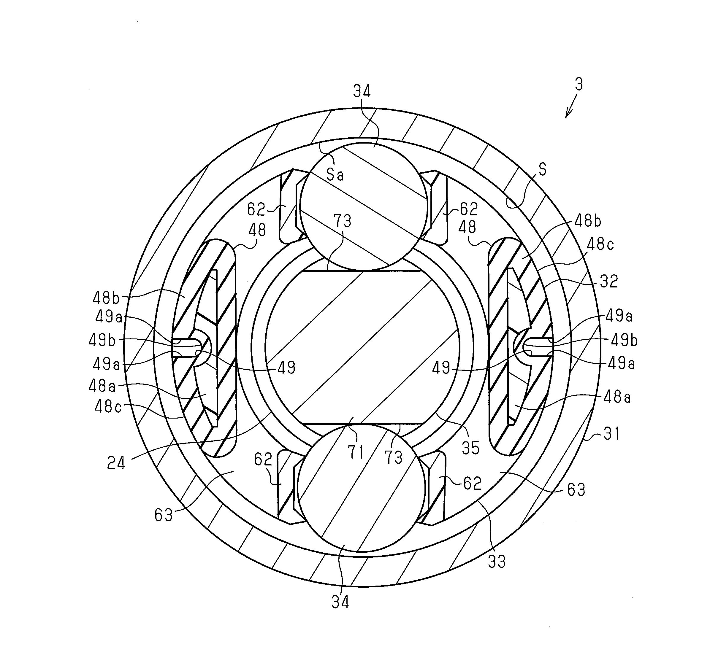
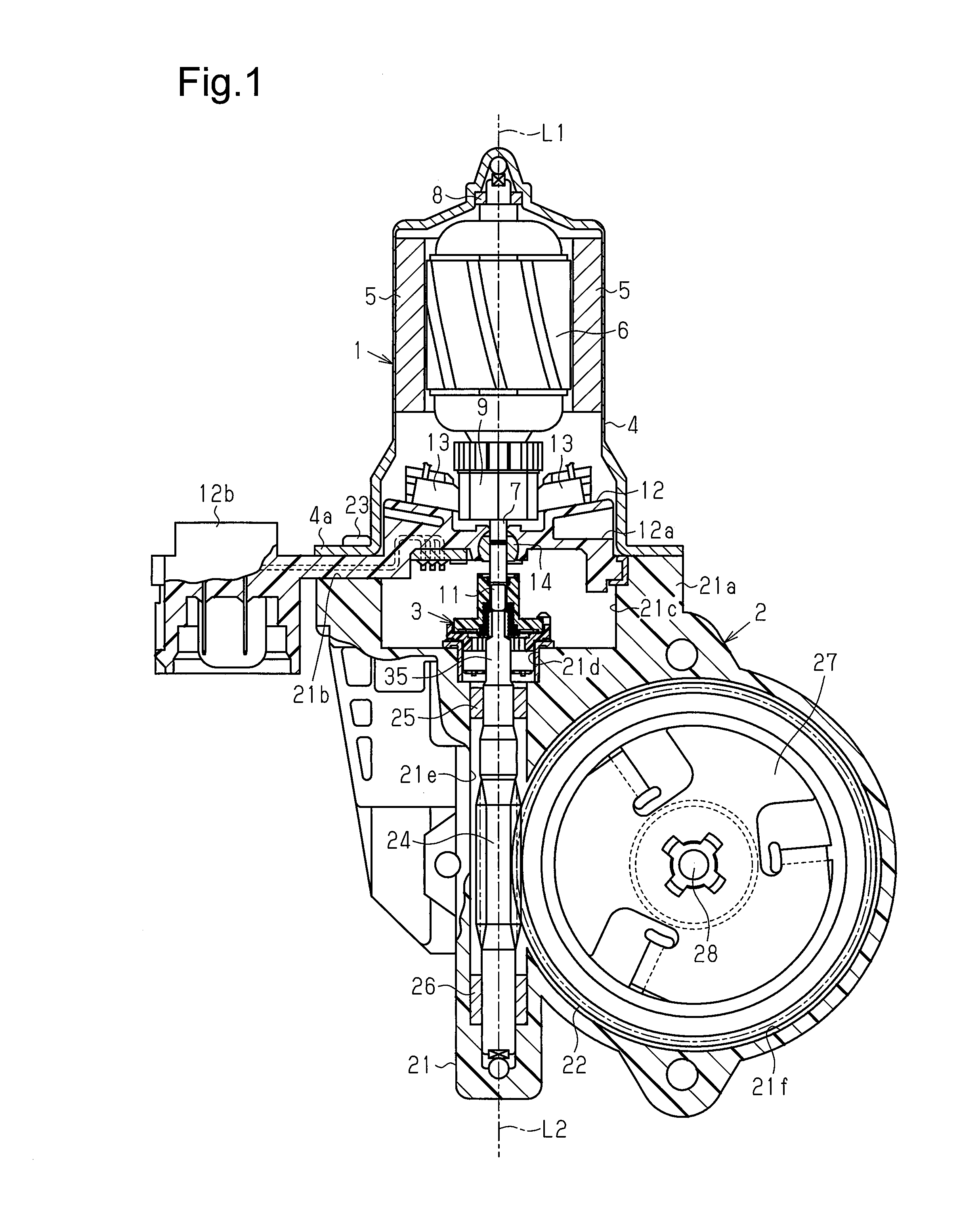
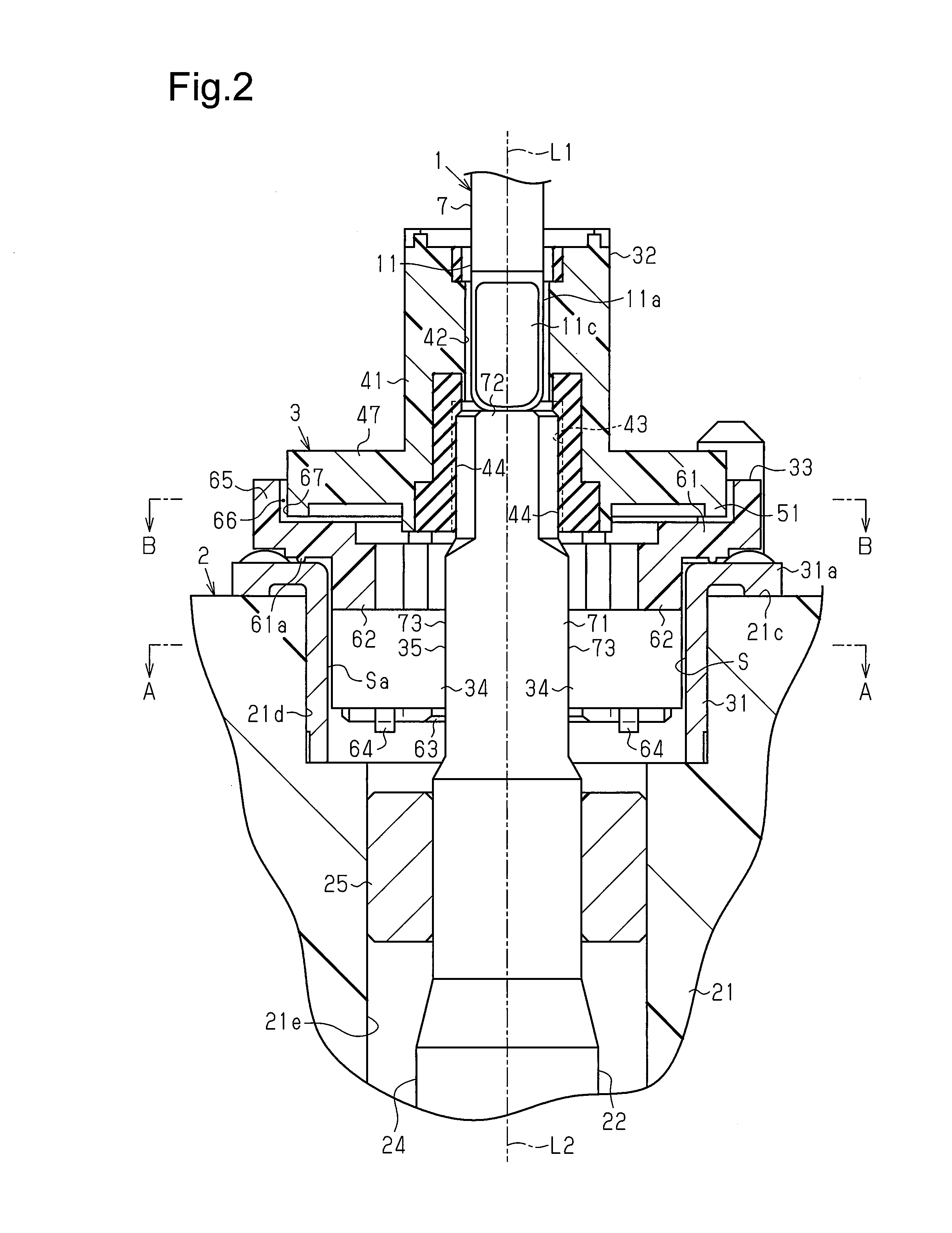
[0025]As shown in FIG. 1, a motor includes a motor unit 1, an output unit 2, and a clutch 3 serving as a coupling portion. The motor of the present embodiment is fixed to a vehicle with the output unit 2 located closer to the ground than the motor unit 1.

[0026]Two magnets 5 are opposed to each other and fixed to an inner circumferential surface of a tubular yoke 4 of the motor unit 1, which has a closed end. An armature 6 is arranged at the inner sides of the magnets 5. The armature 6 includes a rotation shaft 7 located at a central portion of the yoke 4. The rotation shaft 7 includes a basal portion (upper end in FIG. 1), supported by a bearing 8 that is arranged at the center of the closed end of the yoke 4, and a distal portion, to which a tubular commutator 9 is fixed.

[0027]As shown in FIGS. 2 and 3, a drive insertion portion 11 is defined by the distal portion of the rotation shaft 7. The drive insertion portion 11 includes ...


PUM


Abstract

A clutch transmits rotation drive force of a rotation shaft to a driven shaft and restricts transmission of a rotation force from the driven shaft to the rotation shaft. The clutch includes a grease accommodation portion and a rotation member. Grease is arranged in the grease accommodation portion. The grease accommodation portion opens in an axial direction of the rotation shaft. The rotation member is at least partially inserted into the grease accommodation portion and rotated with the rotation shaft about a center axis of the rotation shaft. The rotation member includes a leakage restriction wall that is located toward a radially outer side of the rotation shaft from the opening of the grease accommodation portion and extended in the axial direction of the rotation shaft. The leakage restriction wall is located toward an outer side of the grease accommodation portion from the opening of the grease accommodation portion.

Description

BACKGROUND OF THE INVENTION[0001]The present invention relates to a clutch and a motor.[0002]Japanese Laid-Open Patent Publication No. 2001-336550 describes an example of a motor used for a power window or the like installed in a vehicle. The motor includes a motor unit, which has a rotation shaft that is rotated and driven, and an output unit, which has a worm to which the rotation of the rotation shaft is transmitted and which outputs the rotation transmitted to the worm. A clutch (coupling portion) connects the rotation shaft and the worm. The clutch functions to transmit rotation drive force of the rotation shaft to the worm and not to transmit rotation force from the worm to the rotation shaft.[0003]The clutch includes a coupling member that rotates integrally with the rotation shaft, a driven rotor that is rotatable integrally with the worm and engageable with the coupling member in the rotation direction, and a tubular clutch housing into which the coupling member and the dri...

Claims


Application Information

Patent Timeline
IPC IPC(8): F16D41/066
CPCF16D2300/06F16D41/066F16D43/02F16D2300/22
Inventor OGURI, RYOUSUKE
Owner DENSO CORP
Why Eureka
Eureka Blog
Learn More