
Heated hose and method

Inactive Publication Date: 2017-01-12
PARKER HANNIFIN CORP
View PDF9 Cites 8 Cited by
  • Summary
  • Abstract
  • Description
  • Claims
  • Application Information

AI Technical Summary

Benefits of technology

This patent is about a heated hose assembly that is designed to be self-regulating and efficient in controlling its temperature. The heater device inside the hose is controlled by a thermostat that monitors the temperature. This results in better control over power consumption and more precise heating of the hose. The heated hose assembly prevents or minimizes the formation of condensation or freezing of gases or liquids at low temperatures.

Problems solved by technology

Although conventional systems provide adequate heat, such systems have proven to be inefficiently regulated.
Inefficient regulation has resulted in poor power consumption characteristics and overly expensive operation.

Method used


Image

  • Heated hose and method
  • Heated hose and method
  • Heated hose and method

Examples


Embodiment Construction

[0017]Embodiments of the present invention will now be described with reference to the drawings, wherein like reference numerals are used to refer to like elements throughout. It will be understood that the figures are not necessarily to scale.

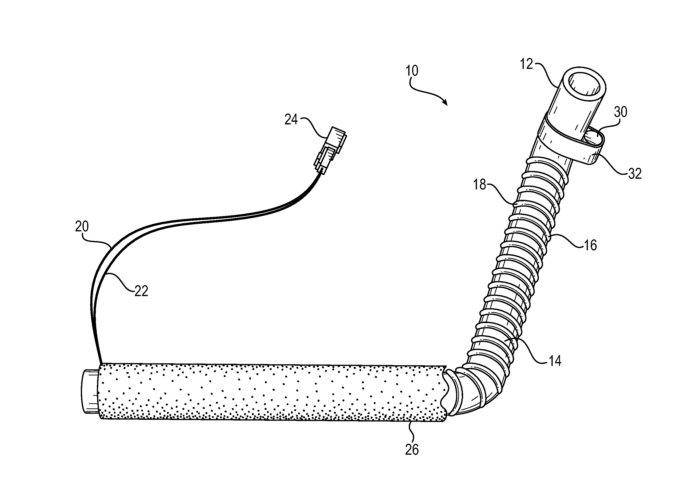
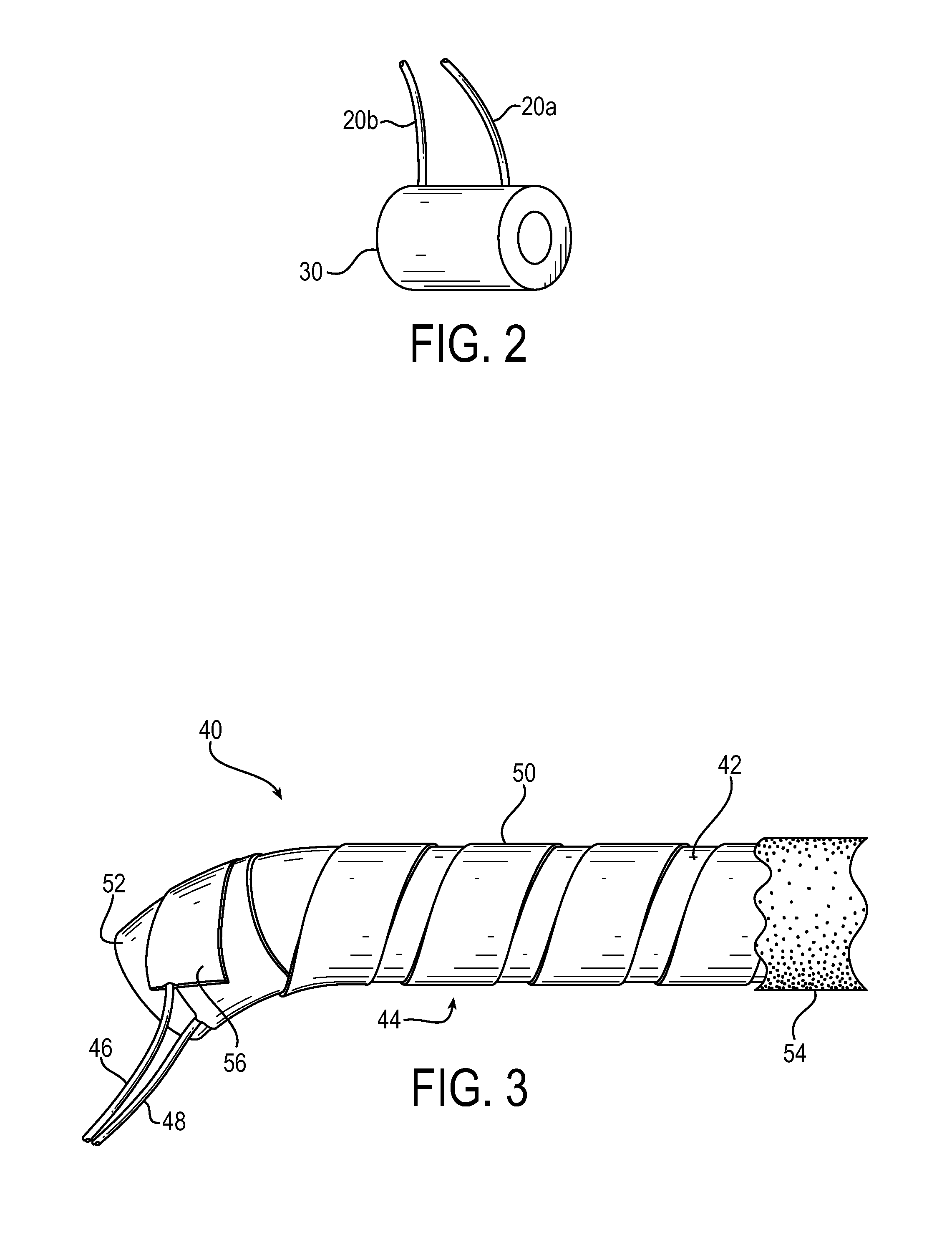
[0018]As aspect of the invention is a heated hose assembly. As further detailed below, in exemplary embodiments the heated hose assembly includes a tubular member (i.e., any suitable hose or like member), a heater device having an electrical resistance element in thermal communication with the tubular member, and a thermal regulating device (e.g., a thermostat) that controls a flow of electrical current through the heater device based on a sensed temperature of the hose assembly. The heat generated by the heater device when the electrical current flows through the resistance element heats the tubular member.

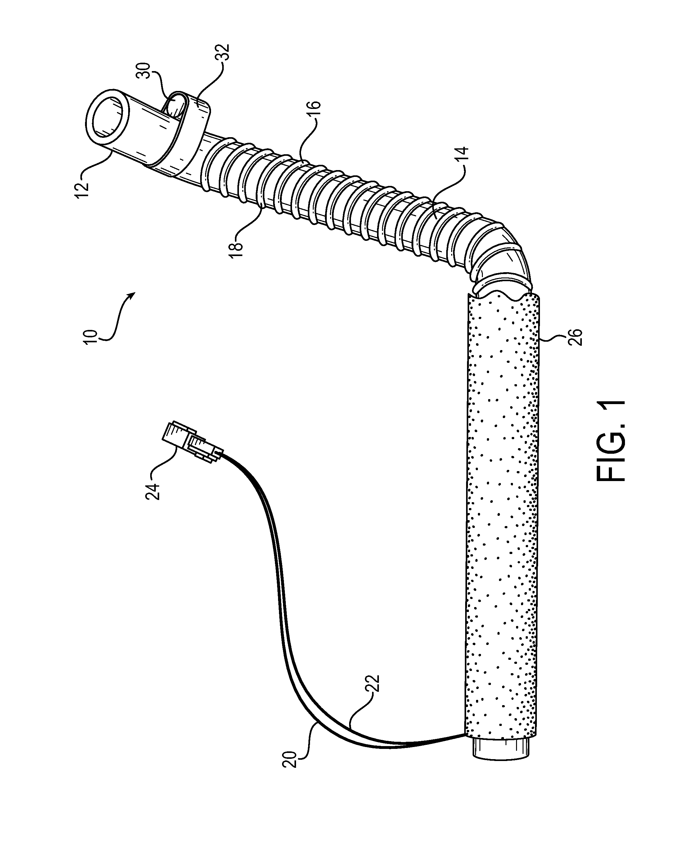
[0019]FIG. 1 is a drawing depicting a plan view of an exemplary heated hose assembly 10 in accordance with embodiments of the present inve...


PUM


Abstract

A heated hose assembly (10) includes a tubular member (12), a heater device (14) having an electrical resistance element (18) in thermal communication with the tubular member (12), and a thermal regulating device (30) that controls a flow of electrical current through the heater device (14) based on a sensed temperature of the hose assembly (10). Heat generated by the heater device (14) when the electrical current flows through the resistance element (18) heats the tubular member (12) to prevent or minimize condensation of gases, or coagulation or freezing of liquids, within the tubular member (12) at relatively low ambient temperatures. A method for controlling a heated hose assembly (10) includes providing the referenced tubular member (12), heater device (14), and thermal regulating device (30), and controlling a flow of current through the heater device (14) based on a sensed hose assembly temperature, wherein heat generated by the heater device (14) when the electrical current flows through the heater device (14) heats the tubular member (12).

Description

RELATED APPLICATION DATA[0001]This application claims priority to U.S. Provisional Patent Application Ser. No. 61 / 939,779, filed on Feb. 14, 2014, the content of which is incorporated here by reference.FIELD OF INVENTION[0002]This invention relates generally to a heated hose assembly, and more specifically relates to an electrically heated hose that prevents or minimizes condensation of gases or coagulation or freezing of liquids within the hose assembly at relatively low ambient temperatures.BACKGROUND OF THE INVENTION[0003]Hoses convey liquids and gases between spaced locations. The term “hose” refers to any generally tubular, elongated member or device and includes flexible, semi-flexible and rigid devices commonly referred to as “hoses,”“tubes,”“pipes” and the like. Hoses may have different cross-sections, and may have for example, round, oval, polygonal or other cross sectional shape. Hoses may be of any material, including, for example, thermosetting, thermoplastic, metallic a...

Claims


Application Information

Patent Timeline
IPC IPC(8): F16L53/00H05B3/58H05B1/02F16L53/38
CPCF16L53/008H05B3/58H05B1/02H05B3/347F16L53/38
Inventor MARUCCI, NICHOLASHENRY, TYAMOS, DAVIDTASKER, WILLIAMSWAILS, MICHAELMAYNARD, ANTHONYPETER, MATTHEW
Owner PARKER HANNIFIN CORP
Learn More