Heating system for load-lock chamber

a technology of heating system and load-lock chamber, which is applied in the direction of mechanical equipment, water supply installation, transportation and packaging, etc., can solve the problems of poor kla performance and corrosion, release of excessive concentration of gases into the environment, etc., and achieve the effect of reducing the time required for carrying out each wet cleaning, reducing the time available for operation, and reducing the amount of corrosive gas condensation

Inactive Publication Date: 2005-12-29
TAIWAN SEMICON MFG CO LTD
View PDF7 Cites 7 Cited by
  • Summary
  • Abstract
  • Description
  • Claims
  • Application Information

AI Technical Summary

Benefits of technology

[0018] In accordance with these and other objects and advantages, the present invention is generally directed to a novel system for heating a load-lock chamber, particularly that of a plasma etching system for etching semiconductor wafer substrates. The load-lock chamber heating system includes a heater that is provided in fluid communication with a gas supply which contains an inert gas such as nitrogen. A gas pump pumps the gas from the gas supply through the heater, and from the heater into the load-lock chamber. The gas heats the load-lock chamber to prevent or minimize condensation of corrosive etching gases onto the interior surfaces of the load-lock chamber as well as the surfaces of substrates contained therein.
[0020] Reduction or elimination of corrosive gas condensation in a load-lock chamber prolongs the time available for operation of the etching or other processing system by reducing the frequency of wet-cleanings required for the load-lock chamber. Furthermore, the time required for carrying out each wet cleaning is reduced because particle contamination caused by gas condensation is correspondingly reduced or eliminated. The lifetime of system elements such as SMIF (standardized mechanical interface) systems used to load wafers into and unload wafers from the processing system is also increased, due to the reduction or elimination of the corrosive gases.

Problems solved by technology

This can cause contamination of wafers 14 therein, as well as contribute to poor KLA performance and corrosion of the loadlock chamber 22, and may cause release of excessive concentrations of the gases into the environment of the station 10 when wafers 14 are loaded into and unloaded from the wafer cassettes 15 in the cassette holders 12.

Method used


Image

  • Heating system for load-lock chamber
  • Heating system for load-lock chamber
  • Heating system for load-lock chamber

Examples


Embodiment Construction

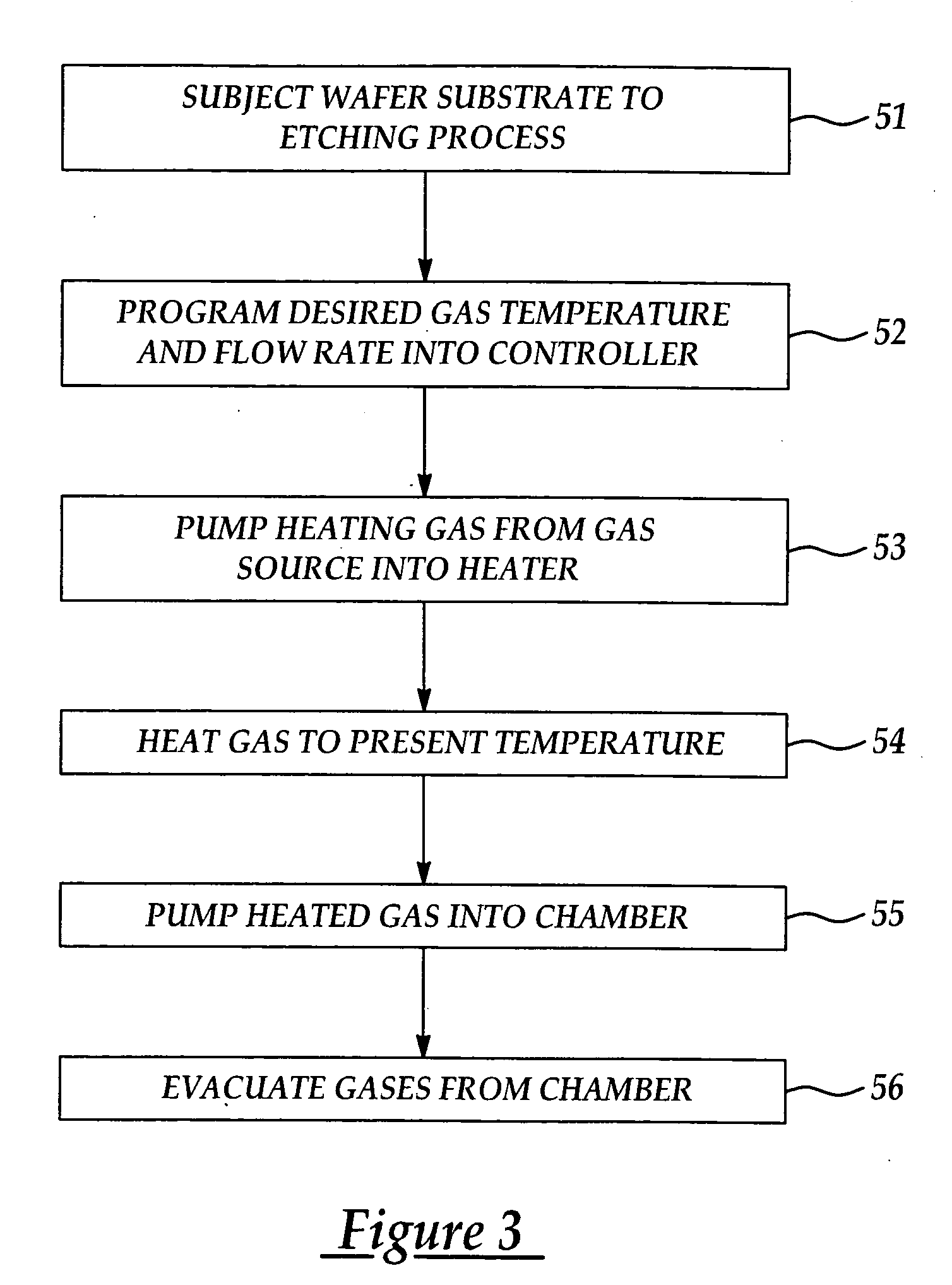
[0025] The present invention has particularly beneficial utility in preventing the condensation of hydrogen bromide, chlorine or other corrosive gases used to etch material layers on semiconductor wafer substrates on the interior surfaces of a load-lock chamber in an etching system. However, the invention is not so limited in application and while references may be made to such etching chambers and load-lock chambers, the invention is more generally applicable to preventing or minimizing condensation of gases on interior chamber surfaces in a variety of industrial and mechanical applications.

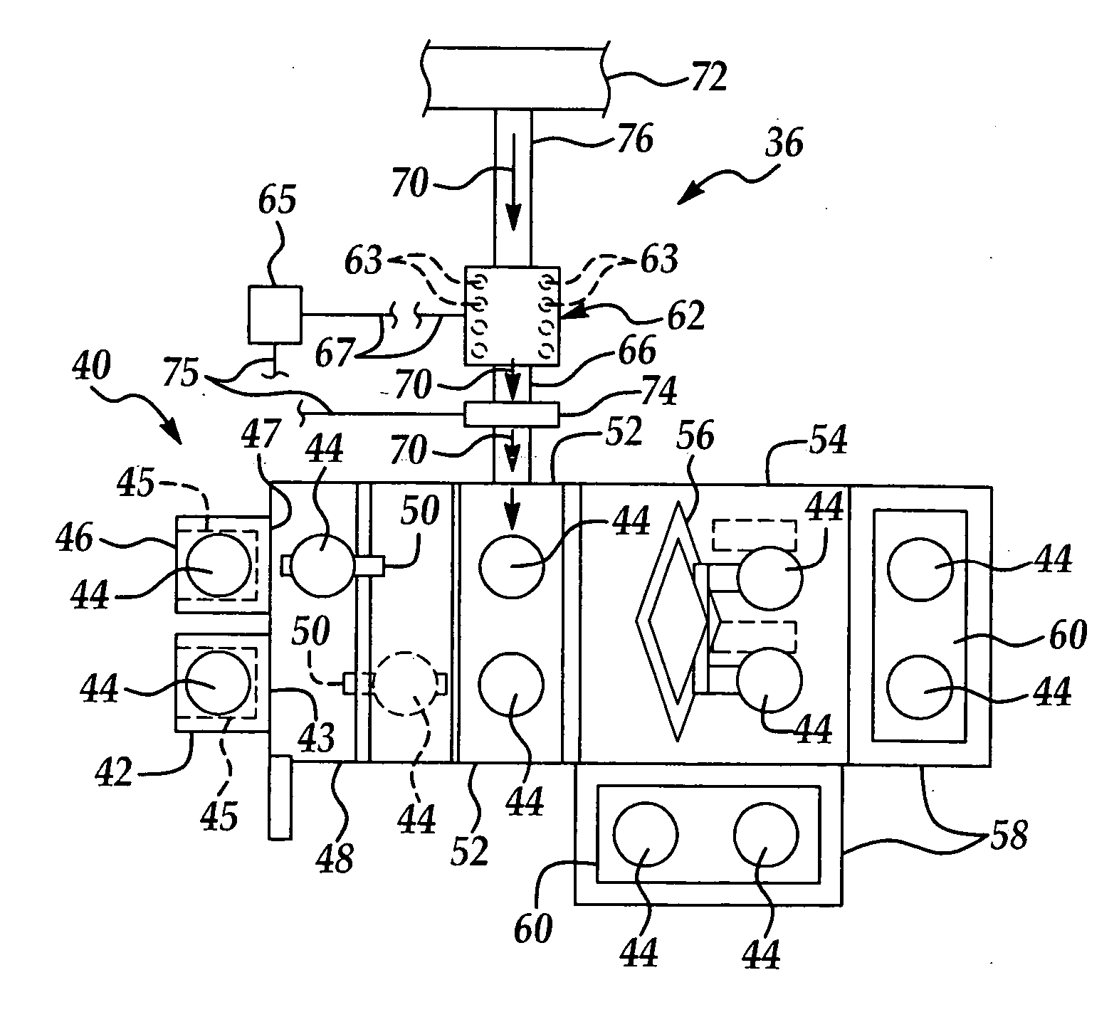
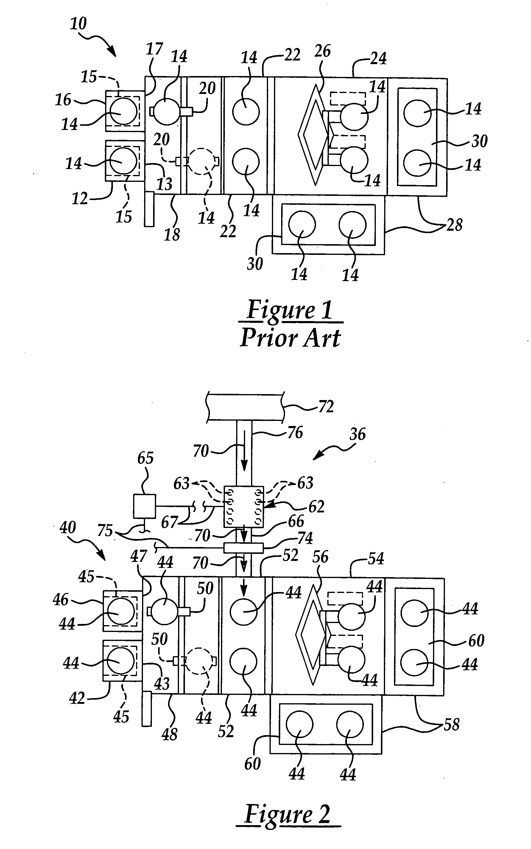
[0026] In a preferred embodiment, the present invention includes a heating system for a load-lock chamber and includes a heater the inlet end of which is provided in fluid communication with a supply of an inert gas such as nitrogen. The outlet end of the heater is provided in fluid communication with the load-lock chamber. A fan, blower or pump is provided for flowing the gas at a selected gas...


PUM

PropertyMeasurementUnit
sizeaaaaaaaaaa
temperatureaaaaaaaaaa
flow rateaaaaaaaaaa

Abstract

A system for heating a load-lock chamber, particularly that of a plasma etching system for etching semiconductor wafer substrates. The load-lock chamber heating system includes a heater that is provided in fluid communication with a gas supply which contains an inert gas such as nitrogen. A gas pump pumps the gas from the gas supply through the heater, and from the heater into the load-lock chamber. The gas heats the load-lock chamber to prevent or minimize condensation of corrosive etching gases onto the interior surfaces of the load-lock chamber as well as the surfaces of substrates contained therein.

Description

FIELD OF THE INVENTION [0001] The present invention relates to etching chambers used in the etching of material layers on a semiconductor wafer substrate to fabricate semiconductor integrated circuits on the substrate. More particularly, the present invention relates to a heating system for heating a loadlock chamber in a semiconductor substrate etching system to reduce or eliminate condensation of etchant gases in the chamber. BACKGROUND OF THE INVENTION [0002] In the semiconductor production industry, various processing steps are used to fabricate integrated circuits on a semiconductor wafer. These steps include deposition of a conducting layer on the silicon wafer substrate; formation of a photoresist or other mask such as titanium oxide or silicon oxide, in the form of the desired metal interconnection pattern, using standard lithographic techniques; subjecting the wafer substrate to a dry etching process to remove the conducting layer from the areas not covered by the mask, the...

Claims


Application Information

Patent Timeline
Patent Type & Authority Applications(United States)
IPC IPC(8): C23F1/00E03B1/00H01L21/00
CPCH01J37/32871H01L21/67207H01L21/67201H01L21/67109Y10T137/0318
Inventor CHEN, WEN-MINGWANG, WEN-CHICHANG, KOU-IEN
Owner TAIWAN SEMICON MFG CO LTD
Why Eureka
Try Eureka