Coil component and manufacturing method thereof

Active Publication Date: 2017-01-12
TDK CORPARATION
View PDF18 Cites 6 Cited by
  • Summary
  • Abstract
  • Description
  • Claims
  • Application Information

AI Technical Summary

Benefits of technology

[0015]According this aspect of the present invention, the terminal electrodes can be easily formed on the outer side surface of each of the flange portions.
[0016]It is preferable that each of the flange portions further has amount surface that is parallel to an axis of the winding core portion, the mount surface has a plurality of ridges and at least one groove, and the winding includes connecting ends of the wires to the ridges of the mount surface. In this case, it is preferable that the forming is performed by immersing the ridges of the mount surfaces in the electrode material while preventing the electrode material from contactin

Problems solved by technology

However, the step of forming the terminal electrodes will be complicated if the outer side of the flange

Method used


Image

  • Coil component and manufacturing method thereof
  • Coil component and manufacturing method thereof
  • Coil component and manufacturing method thereof

Examples


first embodiment

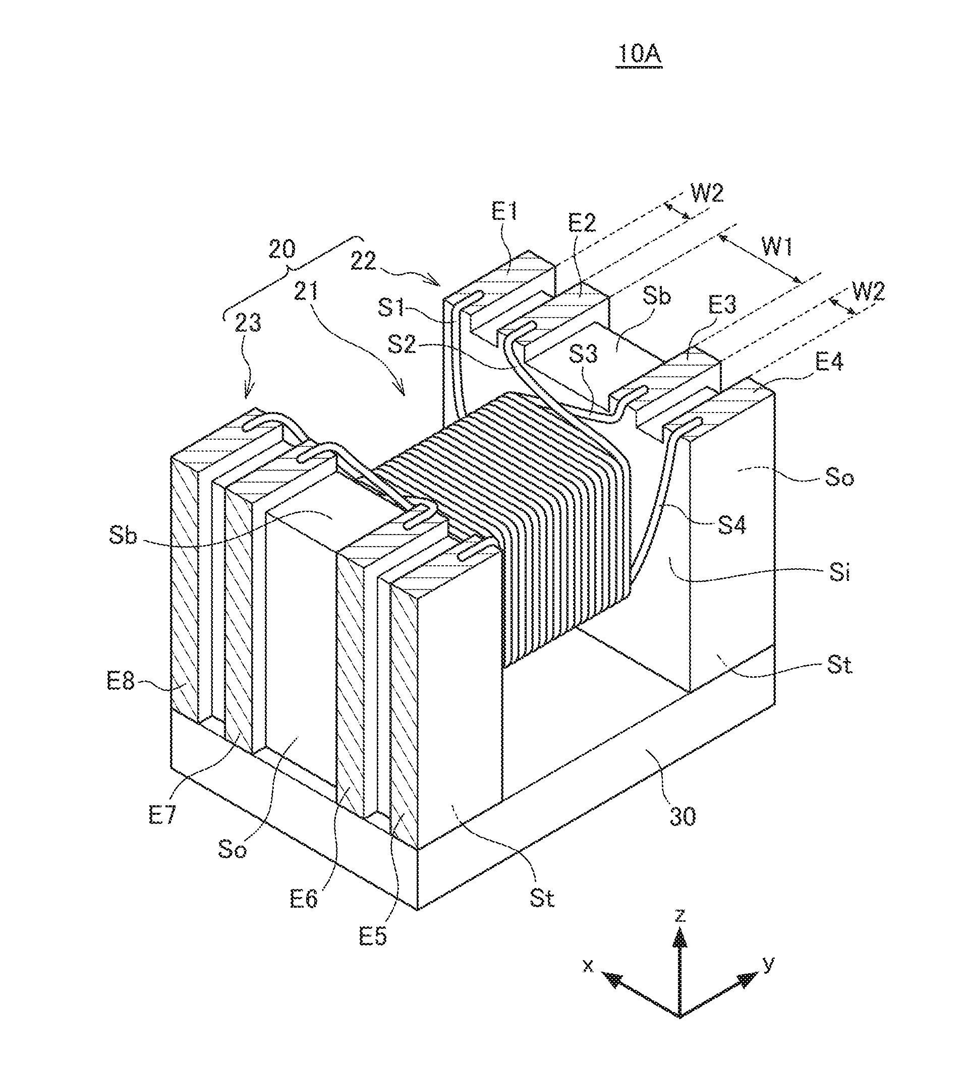
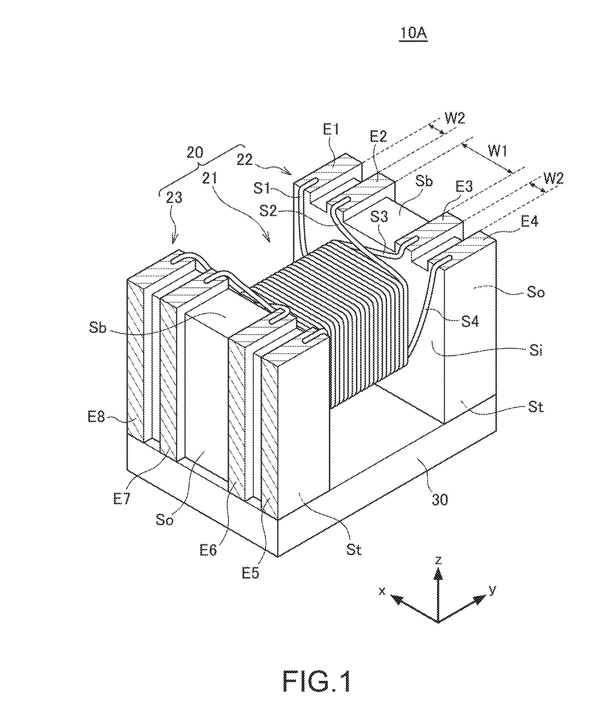
[0028]FIG. 1 is a schematic perspective view showing an appearance of a coil component 10A according to the present invention.

[0029]The coil component 10A of the present embodiment is a pulse transformer of a surface-mount type. As shown in FIG. 1, the coil component 10 includes a drum core 20, a plate core 30 that is bonded to the drum core 20, and conductive wires S1 to S4 that are wound around a winding core portion 21 of the drum core 20. The coil component of the present invention is not limited to the pulse transformer. The coil component of the present invention may be any other transformer component such as a balun transformer or step-up transformer, or may be a filter component such as a common mode choke coil.

[0030]The drum core 20 and the plate core 30 are made of a magnetic material that is relatively high in magnetic permeability such as a sintered composite of Ni—Zn ferrite or Mn—Zn ferrite, for example. Incidentally, the magnetic material that is high in magnetic perm...

second embodiment

[0045]FIG. 4 is a schematic perspective view showing an appearance of a coil component 10B according to the present invention.

[0046]The coil component 10B according to the second embodiment differs from the coil component 10A according to the first embodiment, in that the width in x direction of the ridges formed on the outer side surface So gradually increases, from the mount surface Sb toward the adhesion surface St. The width in x direction of the terminal electrodes E1 to E8 provided on the outer side surface So also gradually increases, from the mount surface Sb toward the adhesion surface St. As a result, the terminal electrodes E1 to E8 provided on the outer side surface So are broader than the terminal electrodes E1 to E8 provided on the mount surface Sb. In any other structural respect, the coil component 10B is identical to the coil component 10A according to the first embodiment. The parts identical to those of the coil component 10A are specified by the same reference nu...

third embodiment

[0048]FIG. 5 is a schematic perspective view showing an appearance of a coil component 10C according to the present invention.

[0049]In the coil component 10C according to the third embodiment, the terminal electrodes E3 and E4 provided on the outer side surface So are integrated into one terminal electrode, and the terminal electrodes E7 and E8 are integrated into one terminal electrode. Hence, on the outer side surface So, the ridges associated with the terminal electrodes E3 and E4 are integrated into one ridge, and the ridges associated with the terminal electrodes E3 and E4 are integrated into one ridge. In any other structural respect, the coil component 10C is identical to the coil component 10A according to the first embodiment. The parts identical to those of the coil component 10A are specified by the same reference numerals, and will not be described repeatedly.

[0050]In the coil component 10C according to the third embodiment, on each outer side surface So, some of the ter...


PUM


Abstract

Disclosed herein is a coil component that includes a drum core including a pair of flange portions and a winding core portion positioned between the flange portions, a plurality of terminal electrodes formed on the flange portions, and a plurality of wires wound around the winding core portion, each end of the wires being electrically connected to an associated one of the terminal electrodes. Each of the flange portions has an inner side surface connected to the winding core portion and an outer side surface opposite to the inner side surface, the outer side surface has a plurality of ridges and at least one groove, and the terminal electrodes are formed on at least the ridges of the outer side surfaces such that the terminal electrodes are isolated from each other by the groove.

Description

BACKGROUND OF THE INVENTIONField of the Invention[0001]The present invention relates to a coil component and a manufacturing method of the coil component, and particularly to a coil component that uses a drum core and a manufacturing method thereof.Description of Related Art[0002]In recent years, electronic components that are used in information terminal devices such as smartphones have been strongly required to be smaller in size and lower in height. Therefore, as for coil components such as pulse transformers, surface-mount coil components that use drum cores instead of toroidal cores have been frequently used. For example, Japanese Patent Application Laid-Open No. 2012-119568 discloses a step-up transformer of a surface-mount type that uses a drum core.[0003]The drum core of the pulse transformer disclosed in Japanese Patent Application Laid-Open No. 2014-199906 includes a flange portion having amount surface and an outer side. As shown in FIG. 2 of Japanese Patent Application L...

Claims


Application Information

Patent Timeline
IPC IPC(8): H01F27/29H01F41/069H01F27/28
CPCH01F27/29H01F41/069H01F27/2823H01F27/027H01F27/2828H01F27/292H01F17/045H01F27/263
Inventor MIKOGAMI, TASUKUTAKAGI, NOBUOOHI, KOUYUASHIZAWA, SYUNTSUCHIDA, SETU
Owner TDK CORPARATION
Why Eureka
Try Eureka