Method of manufacturing nozzle plate and method of manufacturing liquid ejection head
Inactive Publication Date: 2008-09-11
FUJIFILM CORP
View PDF6 Cites 5 Cited by
Summary
Abstract
Description
Claims
Application Information
AI Technical Summary
This helps you quickly interpret patents by identifying the three key elements:
Problems solved by technology
Method used
Benefits of technology
Benefits of technology
[0009]The present invention has been devised in view of these circumstances, an object thereof being to provide a method of manufacturing a nozzle plate and a method of manufacturing a liquid ejection head whereby a highly accurate lyophobic film can be formed readily, even in the case of a nozzle plate having a counterbore section.
Problems solved by technology
However, in a method which embeds a filling material into the nozzles, there is a problem in that it is difficult to fill the material uniformly into all of the nozzles, in such a manner that none of the filling material projects beyond the opening of any of the plurality of nozzles.
In particular, in a nozzle plate in which recess-shaped counterbore sections are formed, it is very difficult to embed a filling material into the nozzles which open respectively at the bottom surface of the counterbore sections in such a manner that there is no projection of the filling material from any of the nozzle openings and in such a manner that the filling material is embedded uniformly into each of the nozzles.
Moreover, in the method described in Japanese Patent Application Publication No. 9-267478, if recess-shaped counterbore sections are formed in the liquid ejection surface of the nozzle plate, then it is very difficult to attach a sheet-shaped elastic body in such a manner that it adheres tightly to the edges of the nozzle openings which are disposed in the bottom surfaces of the counterbore sections, and hence there is a problem in that the lyophobic film in the vicinity of the edges of the nozzles openings is removed and the ejection performance deteriorates.
Furthermore, since the elastic body is damaged when the lyophobic film is removed, then there is another problem in that the elastic body cannot be reused.
Method used
Image
Click on the blue label to locate the original text in one second.
Reading with bidirectional positioning of images and text.
Examples
first embodiment
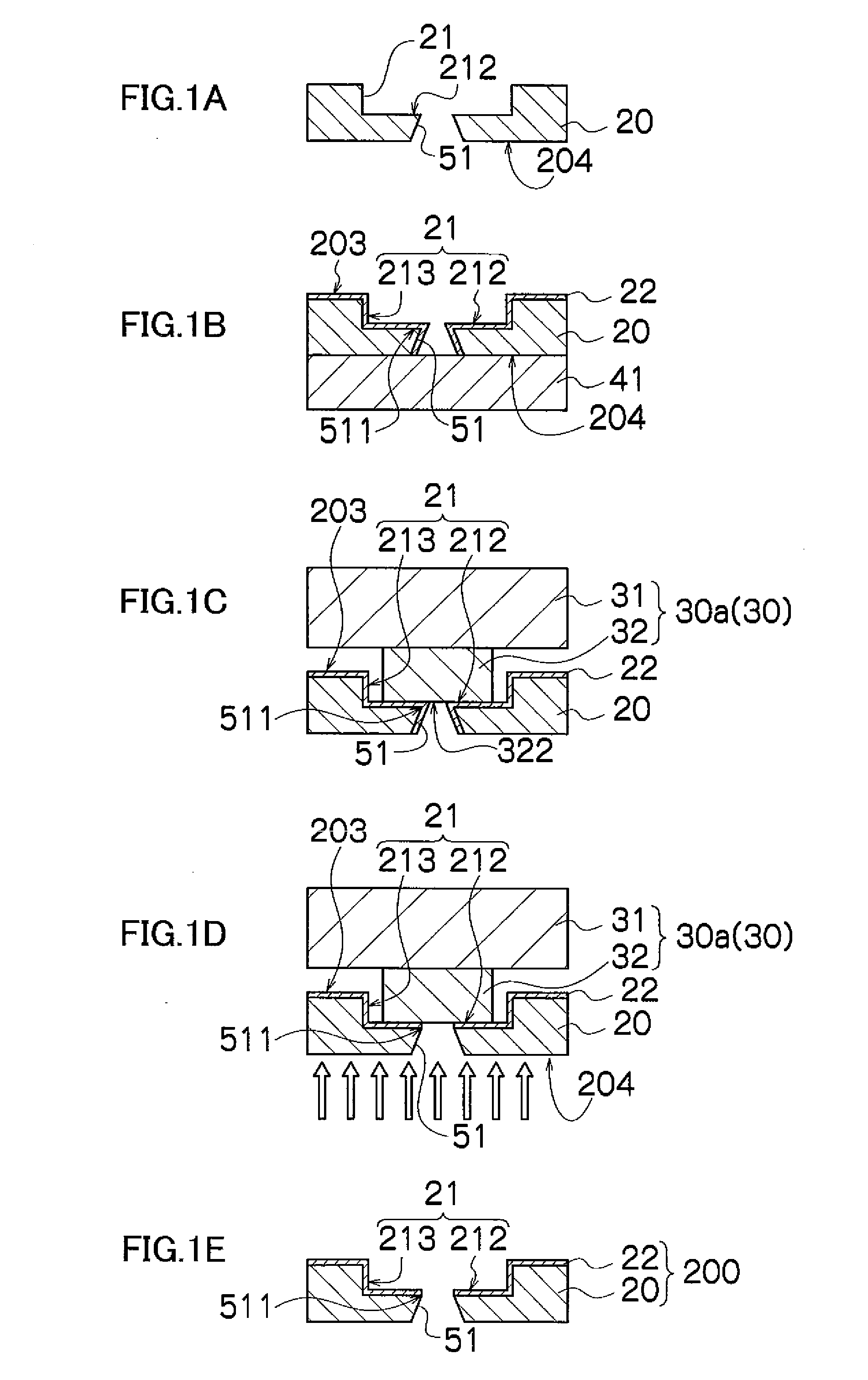
[0047]To begin with, the method of manufacturing a nozzle plate relating to the invention will be described with reference to the step diagrams in FIGS. 1A to 1E.
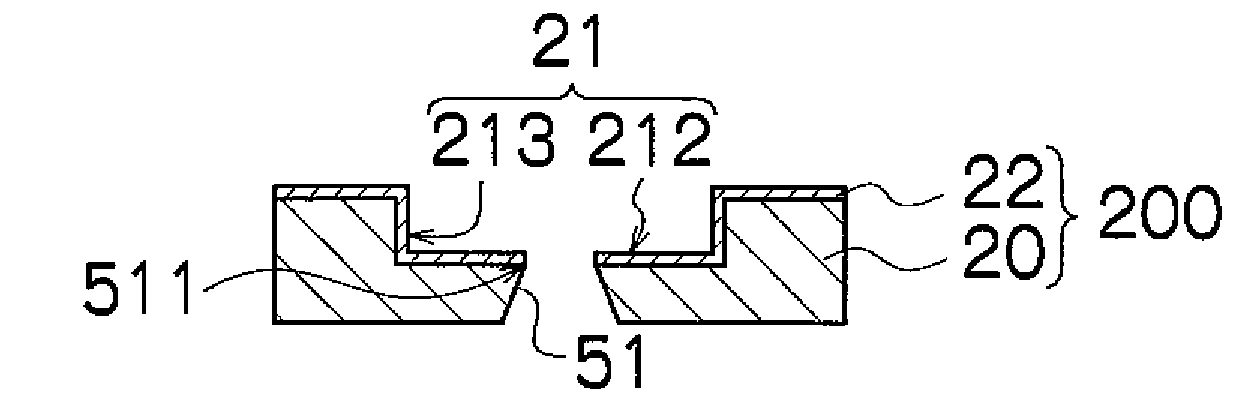
[0048]Firstly, as shown in FIG. 1A, a recess-shaped counterbore section 21 and a nozzle 51 which opens in the bottom face 212 of the counterbore section 21 are formed in a flat substrate. By this means, an initial nozzle plate 20 having counterbore sections 21 and nozzles 51 is obtained.
[0049]Possible materials for the substrate of the nozzle plate 20 include a metal such as stainless steel (SUS), silicon (Si), and the like.
[0050]Possible methods for forming the counterbore sections 21 and the nozzles 51 include electroforming, dry etching, and wet etching.
[0051]The nozzles 51 according to the present embodiment have a tapered shape in which the diameter of the flow channel narrows continuously from the liquid supply surface 204 to the liquid ejection surface, which is the bottom surface 212 of the counterbore section 21, b...
second embodiment
[0070]Next, the method of manufacturing a nozzle plate will be described.
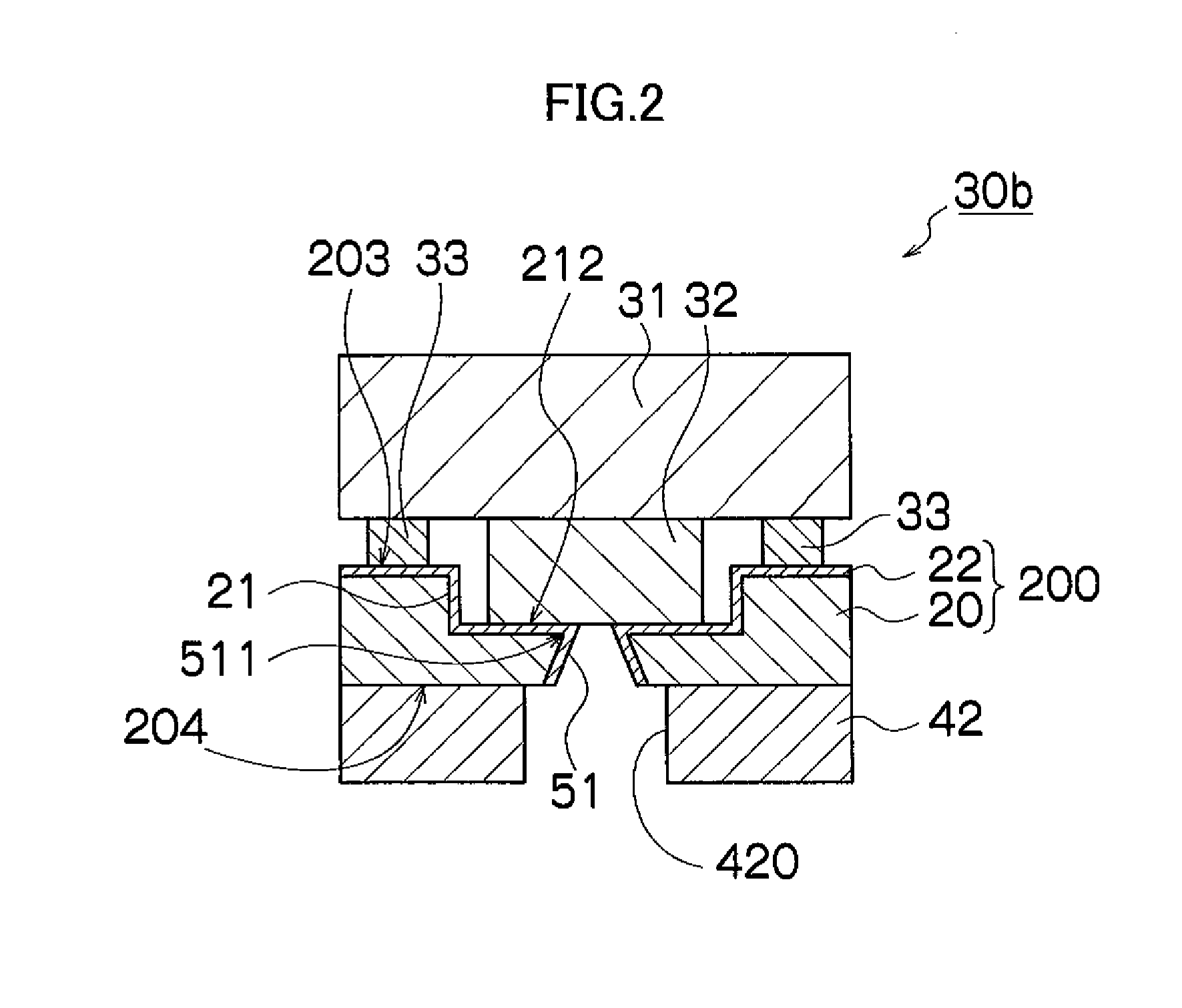
[0071]In the present embodiment, the plate used as the protective plate 30 shown in FIG. 1C and FIG. 1D is one where a film having resistance to the etching performed in the step of removing the lyophobic film 22 shown in FIG. 1D (hereinafter, called “etching-resistant film”) is formed at least on the top surface 322 of the projecting section 32.
[0072]The protective plate 30c shown in FIG. 3A has an etching-resistant film 34 formed only on the top surface 322 of the projecting section 32.
[0073]It is also possible to form an etching-resistant film 34 on the side walls 323 of the projecting section 32 and the flat surface 311 of the flat section 31, as well as on the top surface 322 of the projecting section 32, as shown in FIG. 3B illustrating the protective plate 30d.
[0074]A protective plate 30 (30c, 30d) formed with an etching-resistance film 34 of this kind is used in the process of manufacturing a nozzle p...
third embodiment
[0081]Next, the method of manufacturing a nozzle plate will be described.
[0082]In the present embodiment, the plate used for the protective plate 30 shown in FIGS. 1C and 1D is one having a lyophobic film formed on at least the top surface 322 of the protecting section 32.
[0083]The protective plate 30e shown in FIG. 4A has a lyophobic film 35 formed only on the top surface 322 of the projecting section 32.
[0084]It is also possible to form a lyophobic film 35 on the side walls 323 of the projecting section 32 and the flat surface 311 of the flat section 31, as well as on the top surface 322 of the projecting section 32, as in the protective plate 30d shown in FIG. 4B.
[0085]A protective plate 30 (30e, 30f) formed with a lyophobic film 35 of this kind is used in the process of manufacturing a nozzle plate shown in FIGS. 1A to 1E.
[0086]Furthermore, it is also possible to form the lyophobic film 35 on the whole surface of the protective plate 30 shown in FIGS. 1C and 1D.
[0087]If the top...
PUM
Abstract
The method of manufacturing a nozzle plate includes: a lyophobic film forming step of preparing a nozzle plate having a recess-shaped counterbore section and a nozzle opened in a bottom surface of the counterbore section, and forming a lyophobic film on a surface of the nozzle plate including the bottom surface of the counterbore section of the nozzle plate and at least a portion of an inner wall of the nozzle; an abutting step of preparing a protective plate having a projecting section, and abutting a top surface of the projecting section of the protective plate against the bottom surface of the counterbore section of the nozzle plate in such a manner that the top surface of the projecting section of the protective plate makes tight contact with an opening edge of the nozzle on a liquid ejection side of the nozzle plate; a lyophobic film removing step of removing the lyophobic film from the inner wall of the nozzle of the nozzle plate by etching the nozzle plate from a liquid supply side which is opposite to a side of the nozzle plate that is abutted against the protective plate; and a separating step of separating the protective plate from the nozzle plate.
Description
BACKGROUND OF THE INVENTION[0001]1. Field of the Invention[0002]The present invention relates to a method of manufacturing a nozzle plate and a method of manufacturing a liquid ejection head, by which a lyophobic (liquid-repellent) film is formed on a recess-shaped counterbore section.[0003]2. Description of the Related Art[0004]There are methods for forming a lyophobic film on the liquid ejection surface of a nozzle plate formed with nozzles, in which the lyophobic film is not formed on the inner walls of the nozzles. For example, there are a method in which a lyophobic film is formed only on the liquid ejection surface of a nozzle plate after embedding a filling material into the nozzles, and a method in which a lyophobic film is formed over the whole surface of a nozzle plate, and the unwanted portions are then removed.[0005]Japanese Patent Application Publication No. 9-267478 discloses a method where a lyophobic film is formed on the whole surface of a nozzle plate in which nozz...
Claims
Application Information
Patent Timeline
Application Date:The date an application was filed.
Publication Date:The date a patent or application was officially published.
First Publication Date:The earliest publication date of a patent with the same application number.
Issue Date:Publication date of the patent grant document.
PCT Entry Date:The Entry date of PCT National Phase.
Estimated Expiry Date:The statutory expiry date of a patent right according to the Patent Law, and it is the longest term of protection that the patent right can achieve without the termination of the patent right due to other reasons(Term extension factor has been taken into account ).
Invalid Date:Actual expiry date is based on effective date or publication date of legal transaction data of invalid patent.

