Coil component, manufacturing method thereof, and circuit board on which coil component are mounted

Active Publication Date: 2017-04-20
TDK CORPARATION
View PDF8 Cites 6 Cited by
  • Summary
  • Abstract
  • Description
  • Claims
  • Application Information

AI Technical Summary

Benefits of technology

[0021]In the present invention, the step of forming the first and second external terminals is preferably performed by applying barrel plating to the one and the other ends of the coil pattern. With the above method, it is possible to easily form the first and second external terminals without covering the first and second magnetic members with the first and second external terminals.
[0022]The coil component manufacturing method according to the present invention preferably further includes a step of forming concave portions through each of which the surface of the first magnetic member is exposed by removing, through through holes formed in the uppermost non-magnetic insulating layer, parts of each of non-magnetic insulating layers lower than the uppermost one. The concave portions a

Problems solved by technology

The coil component described in this document is designed to be used for signal transmission, so that it has a thin coil conductor and is thus not suitable for power supply use.
In addition, the coil component described in this do

Method used


Image

  • Coil component, manufacturing method thereof, and circuit board on which coil component are mounted
  • Coil component, manufacturing method thereof, and circuit board on which coil component are mounted
  • Coil component, manufacturing method thereof, and circuit board on which coil component are mounted

Examples


Embodiment Construction

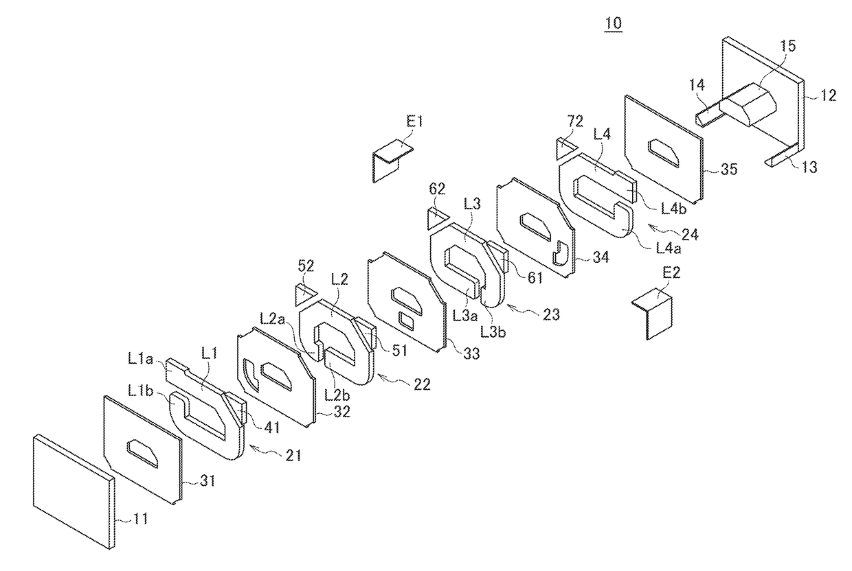
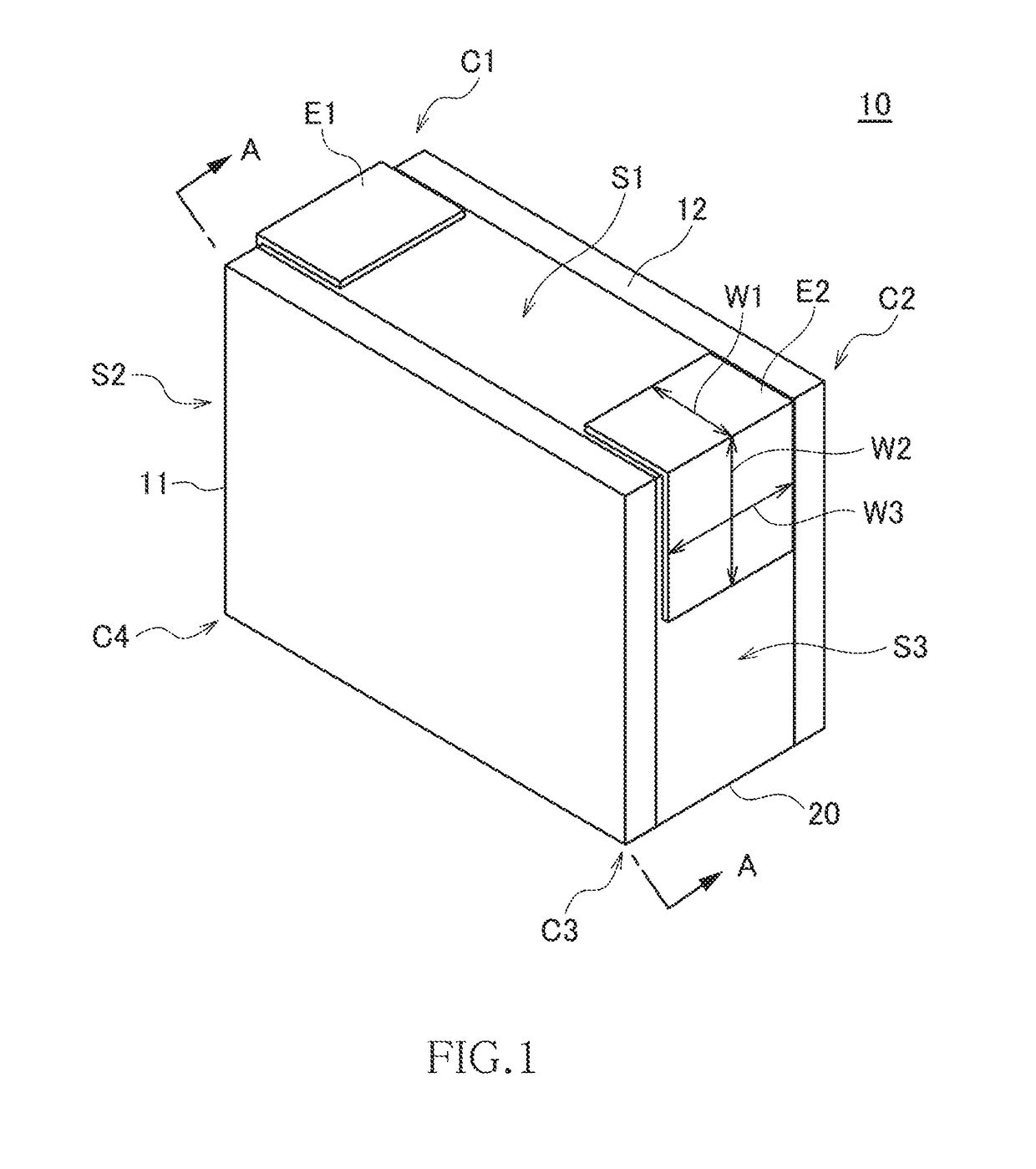
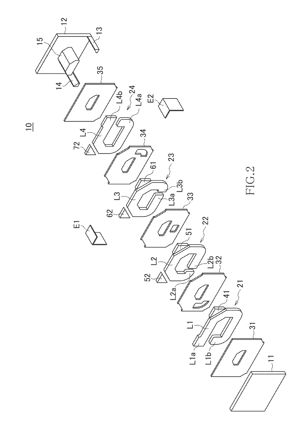
[0033]Preferred embodiments of the present invention will now be explained in detail with reference to the drawings.

[0034]FIG. 1 is a perspective view illustrating the outer appearance of a coil component 10 according to a preferred embodiment of the present invention. FIG. 2 is an exploded perspective view of the coil component 10. FIG. 3 is a cross-sectional view taken along the line A-A illustrated in FIG. 1.

[0035]The coil component 10 according to the present embodiment is a surface-mount type chip component that can be used as an inductor for a power supply circuit. As illustrated in FIGS. 1 to 3, the coil component 10 includes first and second magnetic members 11 and 12 and a coil layer 20 sandwiched between the first and second magnetic members 11 and 12.

[0036]The magnetic member 11 is a substrate made of a magnetic material such as a ferrite. As described later, in the manufacturing process of the coil component 10, the magnetic member 11 is used as a substrate, and the coil...


PUM


Abstract

Disclosed herein is a coil component that includes first and second magnetic members; a coil layer arranged between the first and second magnetic members, the coil layer including a plurality of conductor layers and a plurality of non-magnetic insulating layers, the conductor layers and the non-magnetic insulating layers being alternately laminated, the conductor layers being connected to each other via through holes formed in the non-magnetic insulating layers to form a coil pattern; a first external terminal covering one end of the coil pattern exposed to at least one of side surfaces of the coil layer without covering the first and second magnetic members; and a second external terminal covering other end of the coil pattern exposed to at least one of the side surfaces of the coil layer without covering the first and second magnetic members.

Description

BACKGROUND OF THE INVENTION[0001]Field of the Invention[0002]The present invention relates to a coil component and a manufacturing method therefor and, more particularly, to a coil component suitably used for a power supply circuit and a manufacturing method therefor. The preset invention further relates to a circuit board on which such a coil component is mounted.[0003]Description of Related Art[0004]In a coil component used in a power supply circuit, a current higher than that in a coil component for signal transmission flows, so that the coil component used in a power supply circuit needs to have a lower DC resistance. To reduce a DC resistance, it is necessary to reduce a coil length and to increase the cross-sectional area of a coil conductor. On the other hand, to ensure a sufficient inductance, it is necessary to increase a coil length and to reduce a coil conductor width so as to form a larger loop. Thus, a trade-off relationship exists between the reduction in the DC resist...

Claims


Application Information

Patent Timeline
IPC IPC(8): H01F27/28H01F27/29H01F41/02H05K1/18H01F41/04H01F41/10H01F27/32H01F27/255
CPCH01F27/28H01F27/323H01F27/292H01F27/255H05K2201/1003H01F41/04H01F41/10H01F41/0206H05K1/181H01F17/0013H01F27/2804H01F27/29H01F41/041H01F41/122H01F2017/002H01F2017/0066H01F2027/2809H01F3/10H01F17/04H05K2201/10636H05K3/3442Y02P70/50
Inventor NISHIKAWA, TOMONAGAITO, TOMOKAZUOKUMURA, TAKESHIKAWAMURA, KOUJIWATANABE, TADASHITSUTSUI, HIDENORI
Owner TDK CORPARATION
Why Eureka
Try Eureka