Multi-degree of freedom electromagnetic machine

a multi-degree, electromagnetic machine technology, applied in the field of electromagnetic machines, can solve the problems of mechanical motion technology not keeping up, electronics and sensor technology getting significantly smaller, and the number of electromagnetic machines that involve more than one dof tends to be somewhat large and cumbersom

Active Publication Date: 2017-01-12
HONEYWELL INT INC
View PDF5 Cites 15 Cited by
  • Summary
  • Abstract
  • Description
  • Claims
  • Application Information

AI Technical Summary

Benefits of technology

[0088]As described previously (see FIGS. 6-8 and associated description), the control 1602 associated with the machine 1400 is configured to independently control the current magnitudes and directions in each of the first, second, and third conductors 1406, 1408, 1410, and the frequencies of the currents supplied to each of the first, second, and third conductors 1406, 1408, 1410, to thereby control the rotational speed and the rotational position of the second structure. This avoids momentum singularities in two ways. The first way, which is depicted most clearly in FIG. 32, is by varying the tilt axis 3006 of the wheel 3002 by varying the relative phase between the spin commands and the tilt command, which modifies the momentum vector 3008. This is similar to the known 2-axis gimbal solution described above, but without the additional motor.

Problems solved by technology

Consequently, mechanisms that involve more than one DoF tend to be somewhat large and cumbersome, and therefore inefficient.
While electronics and sensor technologies have gotten significantly smaller in recent years, mechanical motion technology has not kept up.
For example, the longitude coil is physically difficult to wind.
This adds to the overall cost and size, and reduces coil efficiency.
Another drawback is that a separate centering torque is (e.g., springs or a magnetic detent) required to implement open-loop position control of the armature.

Method used


Image

  • Multi-degree of freedom electromagnetic machine
  • Multi-degree of freedom electromagnetic machine
  • Multi-degree of freedom electromagnetic machine

Examples


Embodiment Construction

[0037]The following detailed description is merely exemplary in nature and is not intended to limit the invention or the application and uses of the invention. As used herein, the word “exemplary” means “serving as an example, instance, or illustration.” Thus, any embodiment described herein as “exemplary” is not necessarily to be construed as preferred or advantageous over other embodiments. All of the embodiments described herein are exemplary embodiments provided to enable persons skilled in the art to make or use the invention and not to limit the scope of the invention which is defined by the claims. Furthermore, there is no intention to be bound by any expressed or implied theory presented in the preceding technical field, background, brief summary, or the following detailed description.

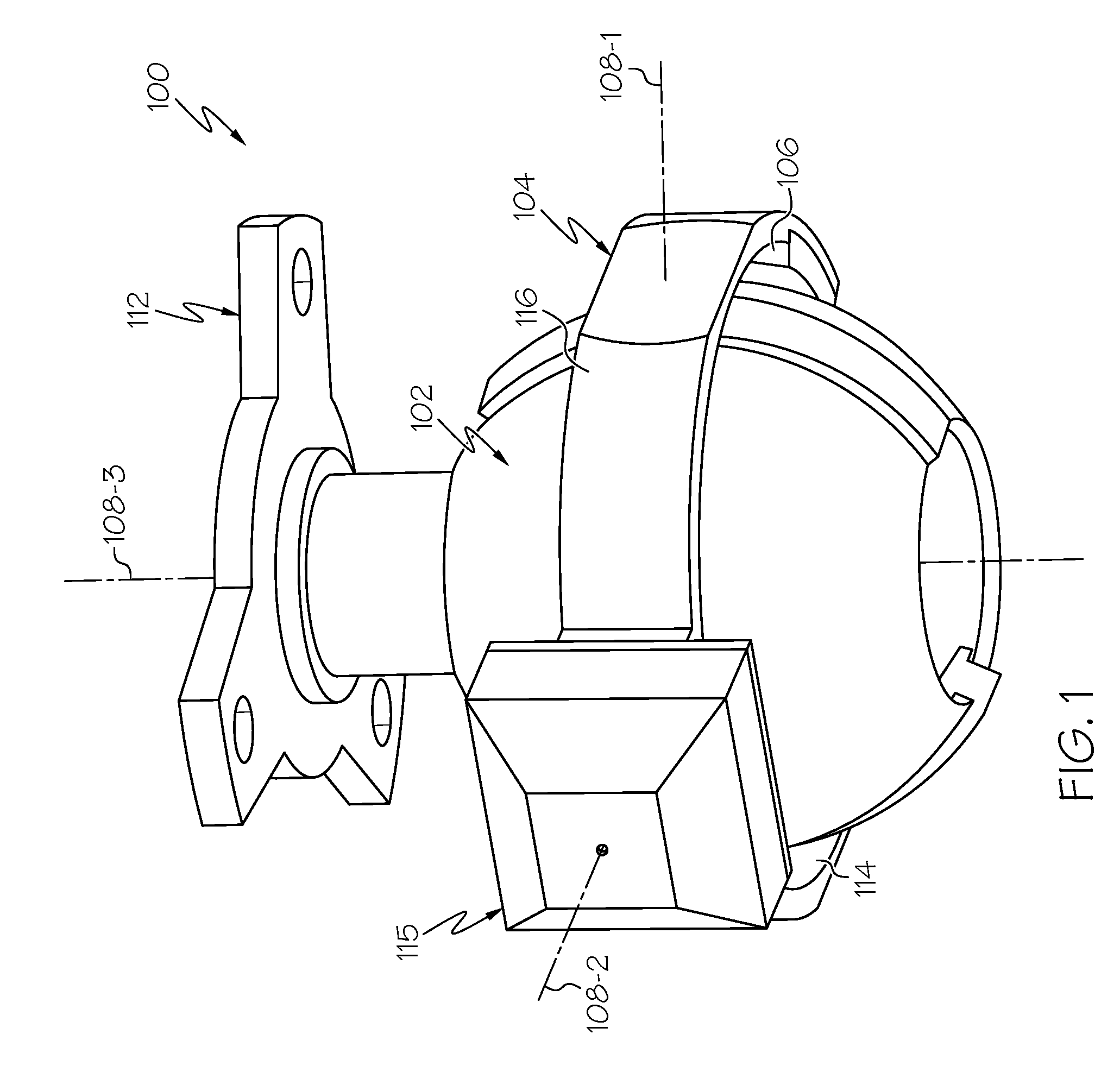
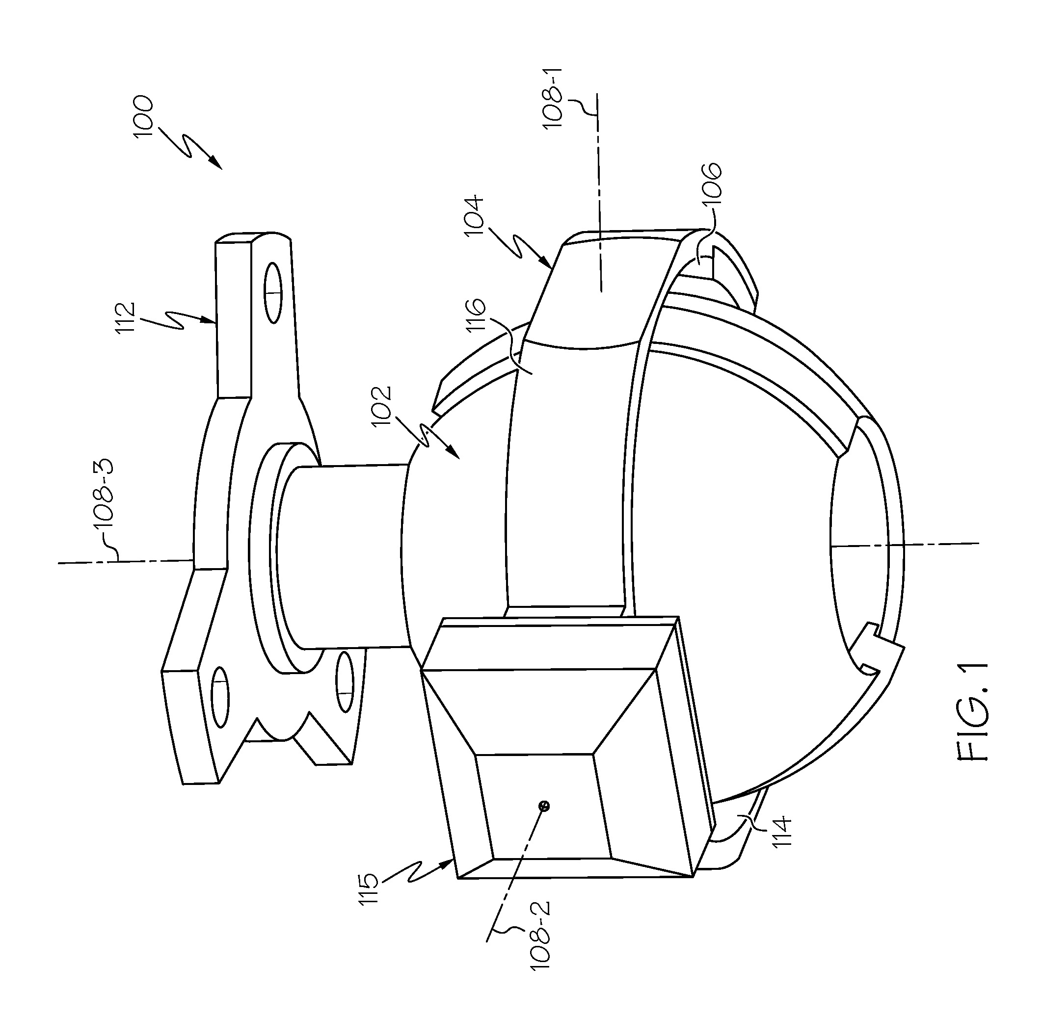
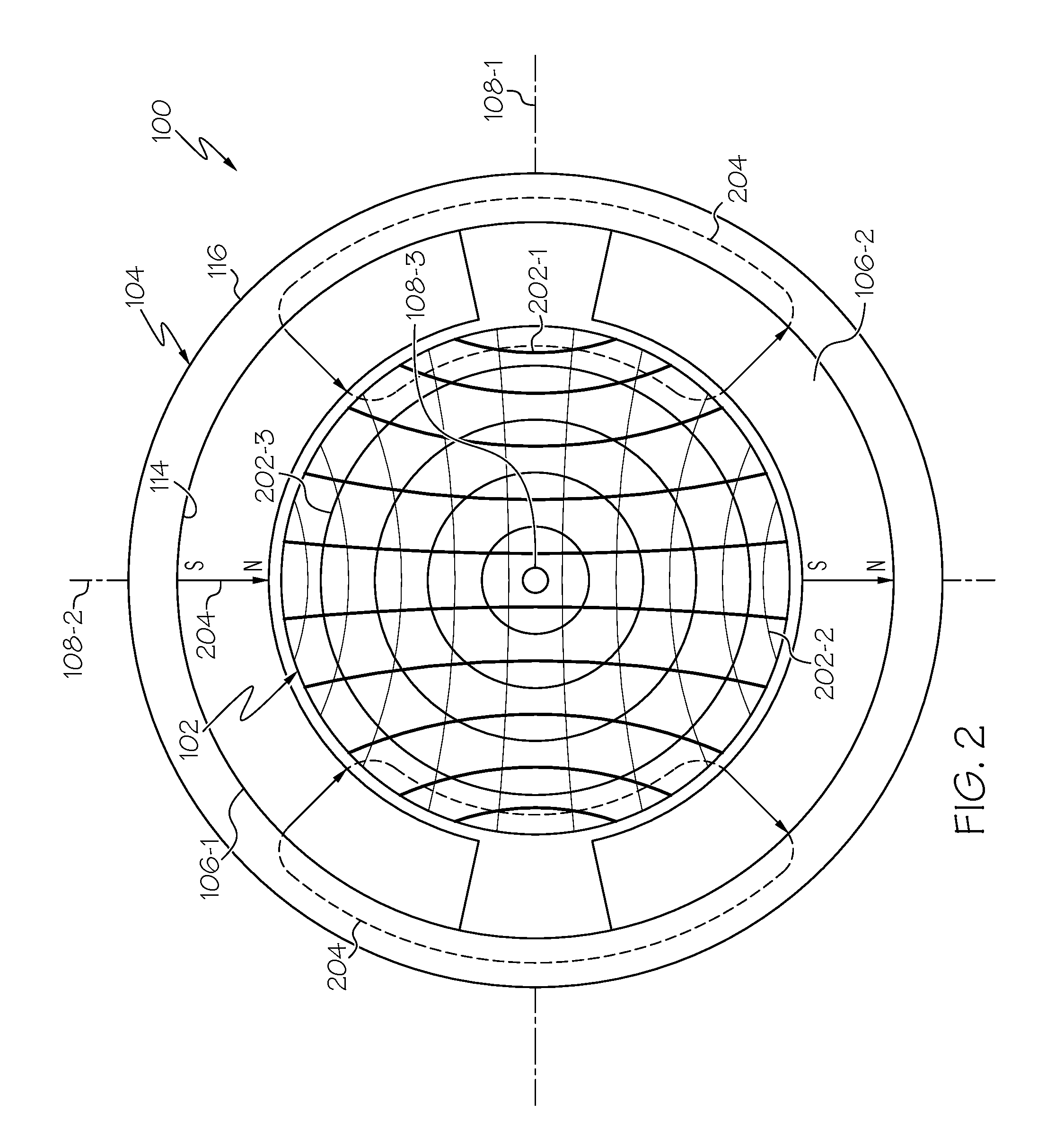
[0038]In this regard, it is noted that the multi-degree of freedom spherical actuator disclosed herein is, for ease of explanation and illustration, generally described as operating as a motor....


PUM


Abstract

A multi-degree-of-freedom electromagnetic machine that may be operated as a motor, a generator, or a motor-generator, includes a first structure and a second structure. The first structure comprises a first conductor, a second conductor, and a third conductor, each of which follows a different trajectory. The first, second, and third conductors together form a general shape of a surface. The second structure is disposed adjacent to the first structure and includes a magnet that emanates a magnetic field. The magnet has at least one of its magnetic poles facing the surface. A Lorentz force affects relative movement between the first structure and the second structure when the magnetic field that emanates from the at least one magnetic pole interacts with electrical currents within any of the electrical conductors.

Description

CROSS-REFERENCE TO RELATED APPLICATION[0001]This application is a continuation-in-part (CIP) of U.S. patent application Ser. No. 14 / 792,799, filed Jul. 7, 2015.TECHNICAL FIELD[0002]The present invention generally relates to electromagnetic machines, and more particularly relates to a multi-degree of freedom electromagnetic machine, such as a motor and / or generator.BACKGROUND[0003]It is generally known that currently available motion control systems that are designed to move an object in more than one degree of freedom (DoF) include a separate motor or actuator for each DoF. More specifically, at least two motors or actuators are needed to implement 2-DoF motion, at least three motors or actuators are needed to implement 3-DoF motion, and so on. Consequently, mechanisms that involve more than one DoF tend to be somewhat large and cumbersome, and therefore inefficient.[0004]While electronics and sensor technologies have gotten significantly smaller in recent years, mechanical motion t...

Claims


Application Information

Patent Timeline
Patent Type & Authority Applications(United States)
IPC IPC(8): H02K7/116
CPCH02K2201/18H02K7/116H02K41/031
Inventor BANDERA, PABLOROTH, HANSCARSON, MARK A.
Owner HONEYWELL INT INC
Why Eureka
Try Eureka