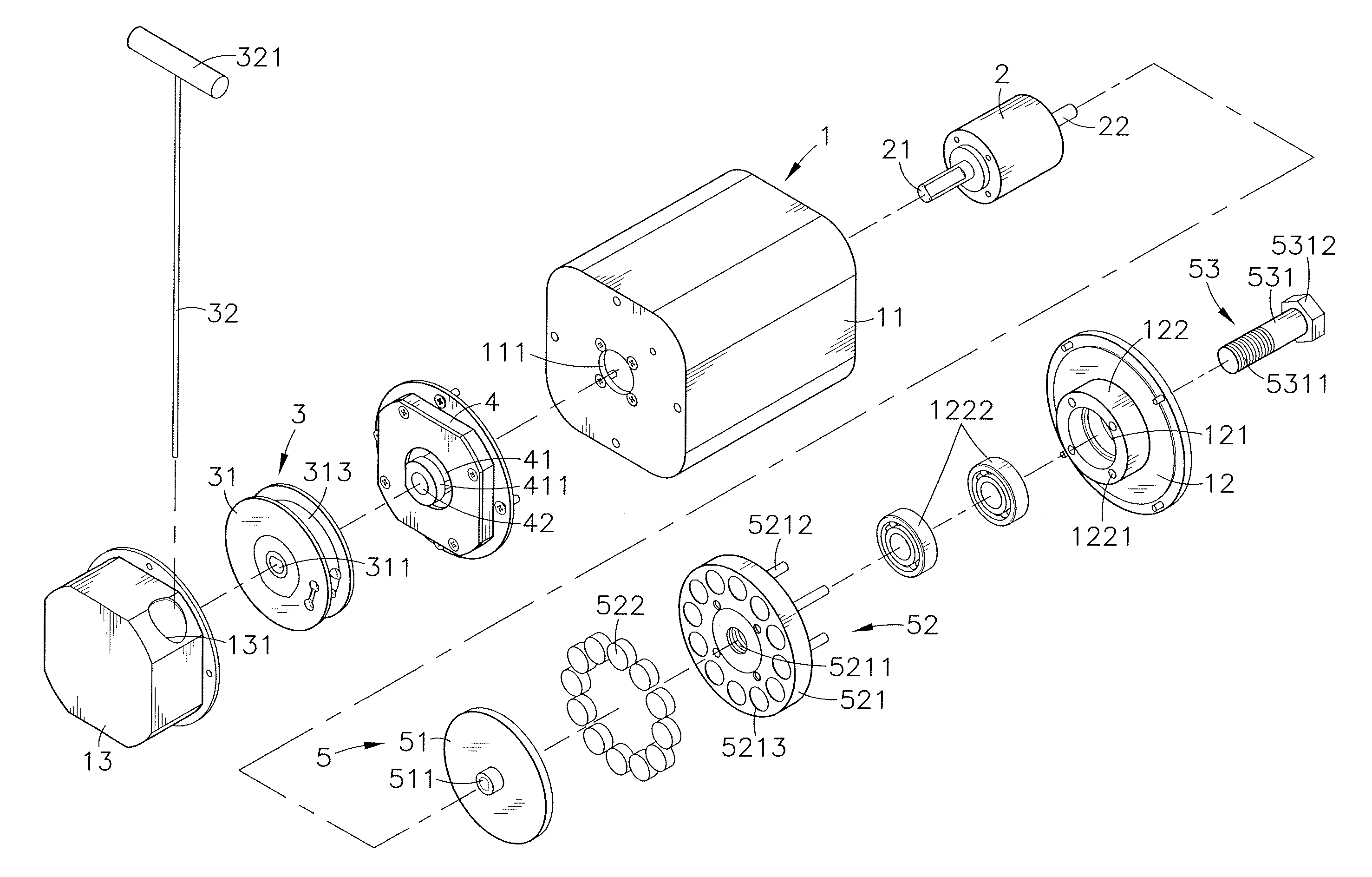
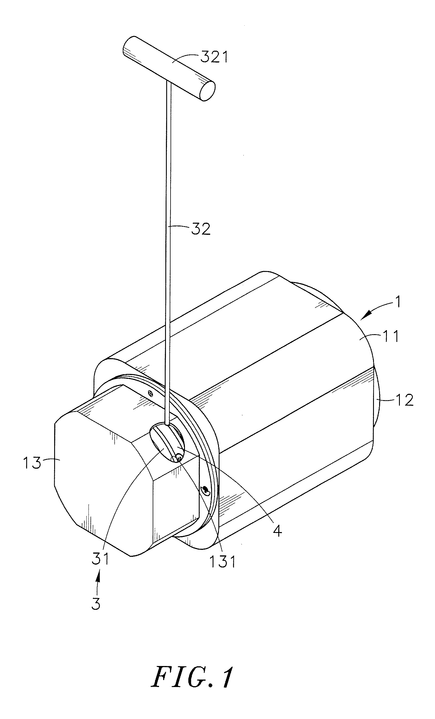
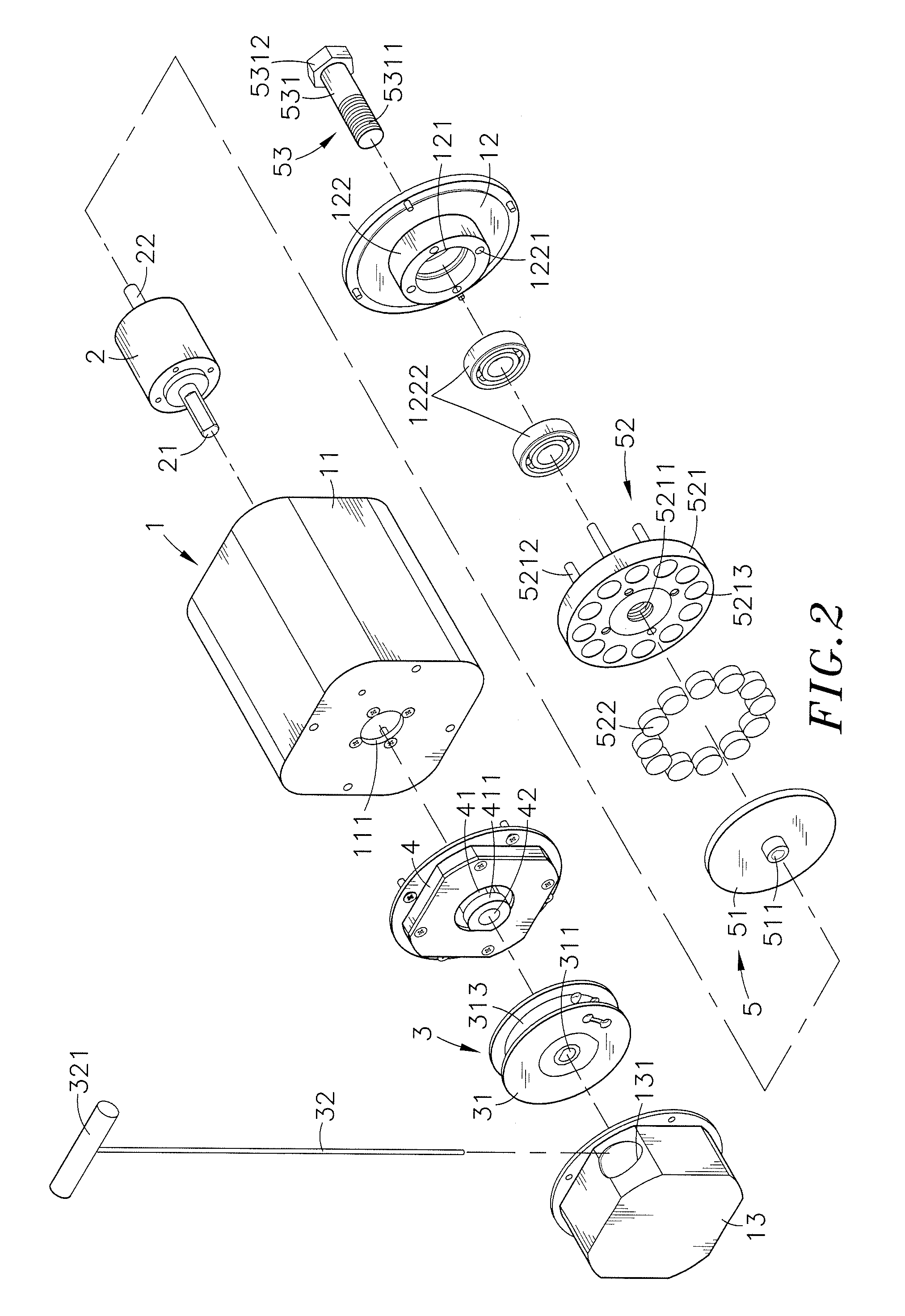
Damping device

a technology of damping device and damping plate, which is applied in the direction of frictional force resistors, gymnastic exercise, sport apparatus, etc., can solve the problems of wear generation between metal elements, noise generation, and reduced life time of fitness equipment, so as to improve the life time and portability of damping device, increase or reduce the length of interval, and improve the strength of pulling force

Inactive Publication Date: 2017-01-19
GLOBAL WIN TECH CO LTD
View PDF17 Cites 17 Cited by
  • Summary
  • Abstract
  • Description
  • Claims
  • Application Information

AI Technical Summary

Benefits of technology

[0010]To solve the problems, the inventor collects related data and performs many tests based on long-term experience, and finally designs a damping device in which an interval is formed between the metal element and the magnetic part, to improve the life time and portability of the damping device.
[0011]Main objective of the present disclosure is to provide a damping device. In the damping device, an interval is formed between the metal element and the magnetic part, and an adjusting member is inserted into the hollow-out hole from the outside of the casing structure to pivotally link with the magnetic part. In practical application, the adjusting member can be used to drive the load plate close to or away from the metal element, so as to increase or reduce a length of the interval and a...

Problems solved by technology

Therefore, wears may be generated between the metal element and the magnet piece and noise may also be generated, and the life time of the fitness equipment is also decreased.
In addition, the fitnes...

Method used


Image

  • Damping device
  • Damping device
  • Damping device

Examples


Embodiment Construction

[0023]Reference will now be made in detail to the exemplary embodiments of the present disclosure, examples of which are illustrated in the accompanying drawings. Therefore, it is to be understood that the foregoing is illustrative of exemplary embodiments and is not to be construed as limited to the specific embodiments disclosed, and that modifications to the disclosed exemplary embodiments, as well as other exemplary embodiments, are intended to be included within the scope of the appended claims. These embodiments are provided so that this disclosure will be thorough and complete, and will fully convey the inventive concept to those skilled in the art. The relative proportions and ratios of elements in the drawings may be exaggerated or diminished in size for the sake of clarity and convenience in the drawings, and such arbitrary proportions are only illustrative and not limiting in any way. The same reference numbers are used in the drawings and the description to refer to the ...


PUM


Abstract

A damping device includes a casing structure, a retarding mechanism, a driving mechanism, a restoring mechanism and a resistance mechanism. An accommodating space is formed in the casing structure to accommodate the retarding mechanism, and a through hole and a hollow-out hole are formed at wall surfaces of two opposite sides of the accommodating space respectively. The retarding mechanism has a main shaft passed through out of the through hole, and a retarding shaft acting simultaneously with the main shaft. The driving mechanism has a wire wheel fastened on the main shaft. The restoring mechanism has a restoring wheel fastened on the wire wheel. The resistance mechanism has a metal element fastened on the retarding shaft, and a magnetic part is disposed between the metal element and the hollow-out hole, and an interval is formed between the magnetic part and the metal element.

Description

BACKGROUND OF THE INVENTION[0001]1. Field of the Invention[0002]The present disclosure relates to a damping device, more particularly to a damping device in which an interval is formed between a metal element and a magnetic part to make the rotating metal element not contact with the magnetic part and avoid generating any wear. In addition, the magnitude of a pulling force for the damping device can be adjusted by adjusting a distance between the metal element and the magnetic part without using electric power. Therefore, the life time and carrying convenience of the damping device of the present disclosure can be improved and the noise generated by the damping device of the present disclosure can be reduced.[0003]2. Description of the Related Art[0004]Today, as health consciousness surges, the people pay more attention on body health. Apart from taking care of nutrition absorption of the body in food and drink, the people also train muscles of each of the body portions by executing...

Claims


Application Information

Patent Timeline
IPC IPC(8): A63B21/018A63B21/22
CPCA63B21/018A63B2209/08A63B21/22A63B23/1263A63B23/1272A63B23/1281A63B23/14A63B21/00069A63B21/005A63B21/0052A63B21/151A63B21/4035A63B21/153A63B2022/0079A63B21/0051
Inventor LIN, SHIH-JEN
Owner GLOBAL WIN TECH CO LTD
Why Eureka
Try Eureka