Electrophoretic device, electrophoretic display, and electronic apparatus

a technology of electrophoretic display and electrophoretic device, which is applied in the direction of optics, instruments, optical elements, etc., can solve the problems of reducing the lifetime of electrophoretic display, providing insufficient water blockage and the like, and achieving satisfactory moisture resistance and preventing water penetration

Inactive Publication Date: 2010-11-16
SEIKO EPSON CORP
View PDF4 Cites 3 Cited by
  • Summary
  • Abstract
  • Description
  • Claims
  • Application Information

AI Technical Summary

Benefits of technology

[0019]In the above-described electrophoretic device, in the case where the main surface of the electro-optical panel is used as a display portion or the like, a seamless portion of the protective film can be used as the third portion, thus improving visual identification. The seamless portion can be used as the third portion, thus reducing the effect of degradation factors, such as air and water, to the main surface.
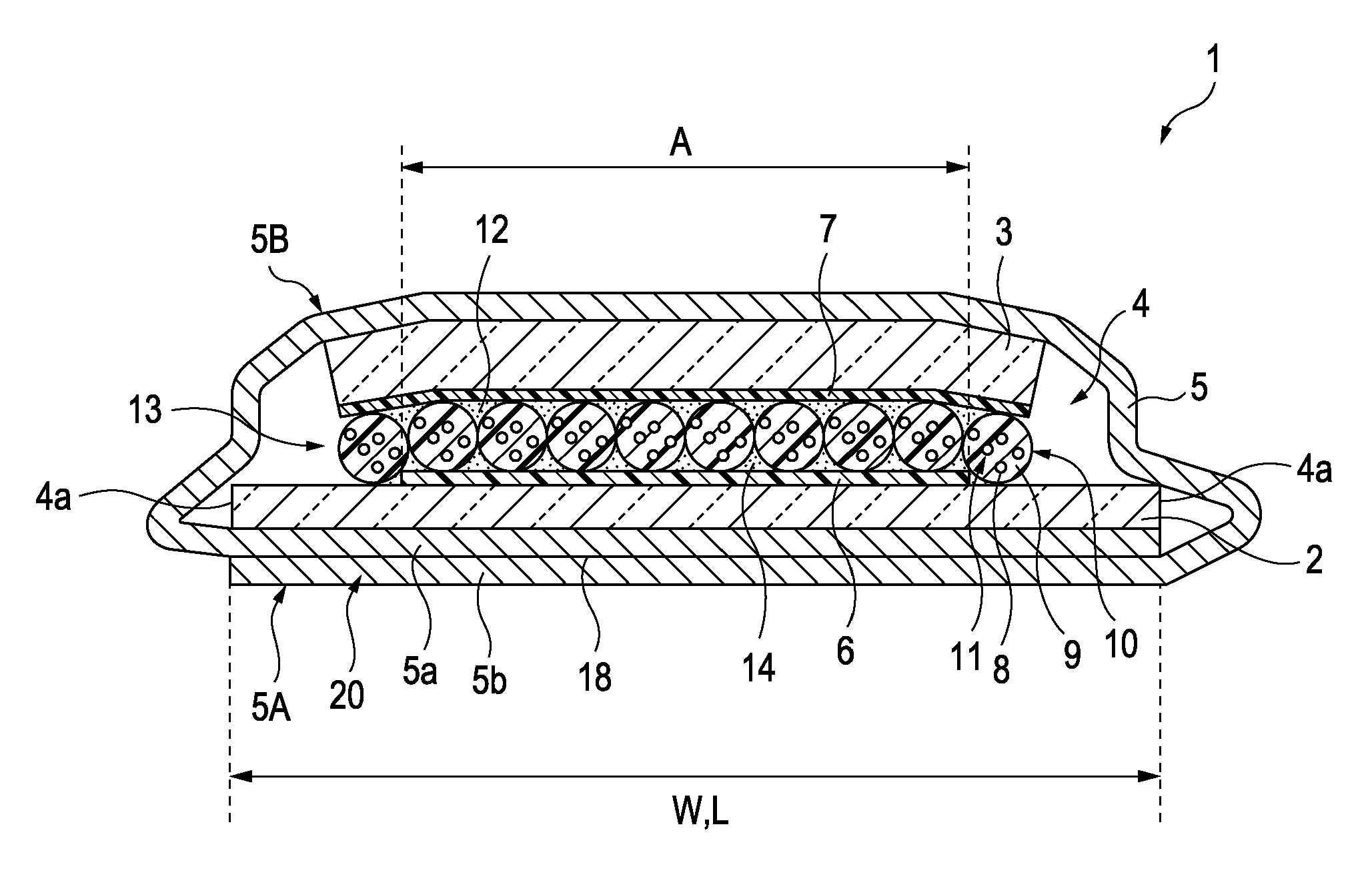
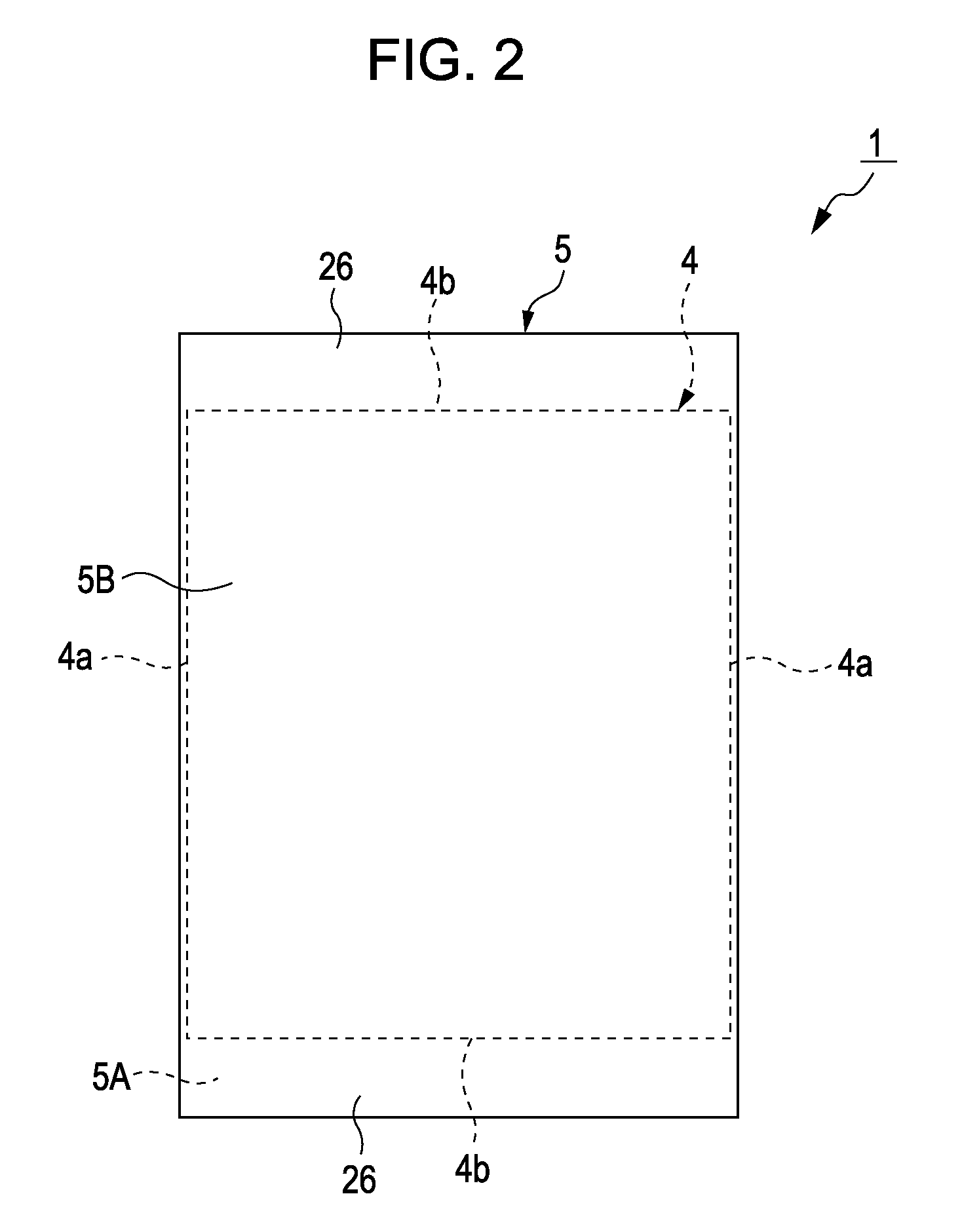
[0032]According to the invention, the display unit is enclosed with the single protective film, and the ends are overlapped and fixed at one of the front side and the back side of the display unit, thus reducing the sealing region that may undergo the penetration of water and the like. This reduces the number of paths for the penetration of water and the like, thus enhancing sealing properties and improving moisture resistance. Furthermore, according to the invention, the folded seal is disposed at one of the front side and the back side, thus eliminating seals disposed at both sides of the display unit in the folding direction. As a result, the protrusion of seals all around the display unit is eliminated, thus resulting in the miniaturization of the display unit. Furthermore, the overlap width of the folded seal such that the penetration of water and the like can be sufficiently inhibited can be ensured, thus improving sealing properties. The penetration of water can be inhibited with high reliability, thus preventing the degradation of the microcapsules in the display unit and imparting satisfactory moisture resistance to the display unit. This can prevent a degradation in display performance and markedly improve the durability and life time of the display unit, thus maintaining satisfactory display performance over long periods of time.
[0034]According to the structure, the folded seal is disposed at the back side of the display unit. For example, the front side of the display unit functions as a display surface where a viewer visually identifies an image, thus providing a satisfactory image for the viewer. Hence, the viewer can visually identify a clear image with comfortable feeling. Moreover, the folded seal is disposed at the backside of the display unit; hence, the aesthetics of the product is not degraded.
[0038]According to the structure, the overlap width is designed to range from half the length of the short side to the length of the short side, thus sufficiently inhibiting the penetration of water and the like. Hence, the moisture resistance at the folded seal is further improved, and the degradation in display performance due to the penetration of water and the like can be prevented. Thereby, the reliability as the product can be ensured.
[0040]This structure includes the electrophoretic display which has satisfactory moisture resistance and prevents the penetration of water and the like in air into the display unit. Thus, a high-quality, high-reliability electronic apparatus can be provided.

Problems solved by technology

In the case where plastic substrates are used in electrophoretic displays, plastic substrates allow water in air to permeate therethrough, thus providing insufficient blockage of water and the like.
The degradation of the microcapsules disadvantageously reduces the lifetime of the electrophoretic displays.

Method used


Image

  • Electrophoretic device, electrophoretic display, and electronic apparatus
  • Electrophoretic device, electrophoretic display, and electronic apparatus
  • Electrophoretic device, electrophoretic display, and electronic apparatus

Examples


Embodiment Construction

[0050]The invention will be described in detail below.

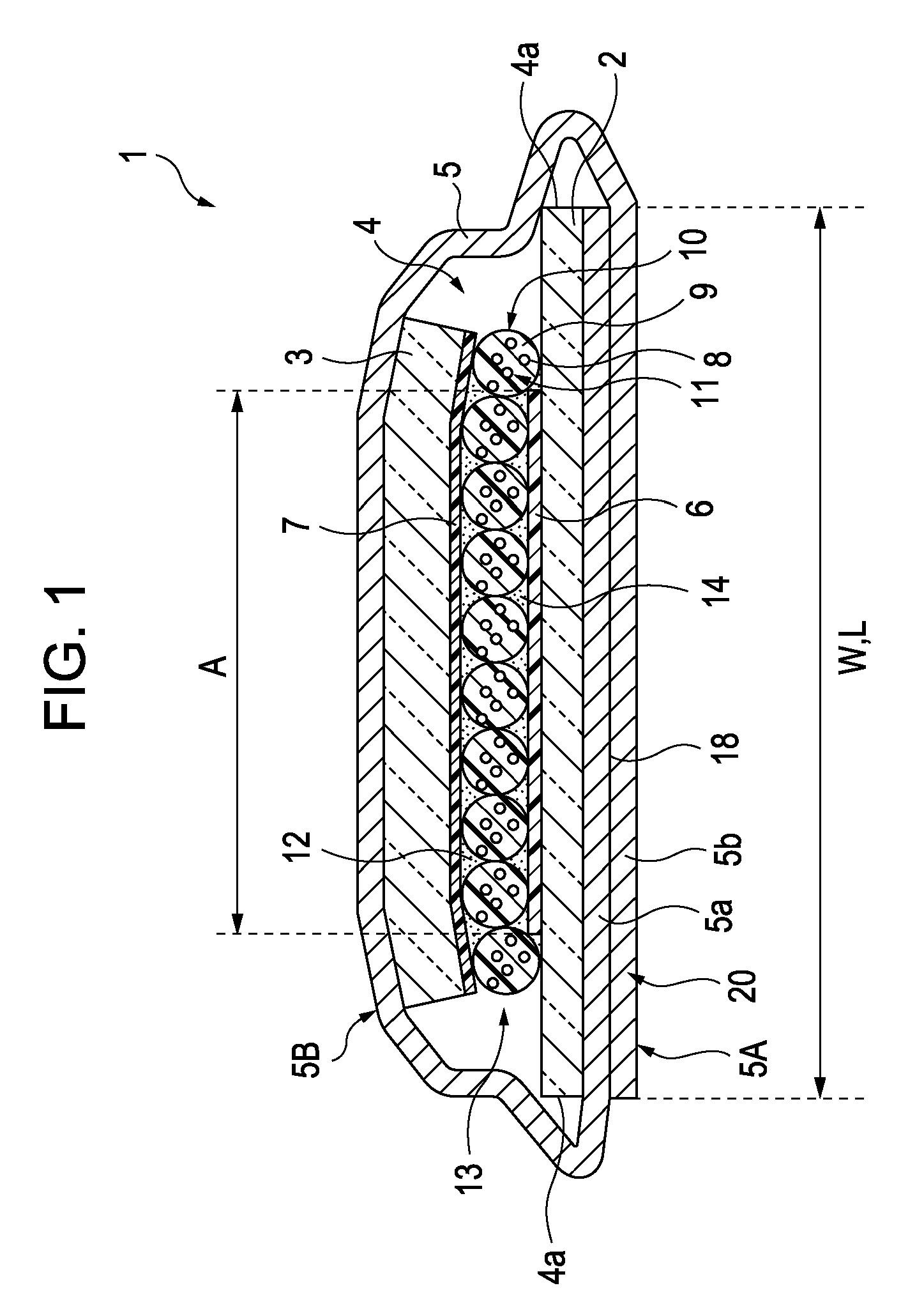
[0051]FIG. 1 shows an embodiment of an electrophoretic display 1 of the invention. In FIG. 1, reference numeral 1 represents an electrophoretic display. The electrophoretic display 1 includes a display unit 4 having a rectangular shape when viewed in plan; and a single protective film 5 with which the entire display unit 4 is enclosed. The display unit 4 includes a first substrate 2 having a segment electrode 6 (driving electrode); a second substrate 3 having a common electrode 7, the second substrate 3 being opposite the first substrate 2; and an electrophoretic layer 13 held by the substrates 2 and 3. The electrophoretic layer 13 has many microcapsules 10 each including an electrophoretic dispersion 11 containing a liquid-phase dispersion medium 9 and electrophoretic particles 8. The electrophoretic display 1 displays an image by applying an electric field to the electrophoretic dispersion 11 to change the distribution state of...


PUM

PropertyMeasurementUnit
diameteraaaaaaaaaa
lengthaaaaaaaaaa
electric fieldaaaaaaaaaa

Abstract

An electrophoretic device includes an electro-optical panel including an electrophoretic layer having an electrophoretic dispersion containing electrophoretic particles dispersed in a liquid-phase disperse medium, wherein the electro-optical panel is enclosed with a single protective film folded, and a first portion of the protective film is bonded to a second portion of the protective film at a first bonding portion.

Description

BACKGROUND[0001]1. Technical Field[0002]Several aspects of the present invention relate to an electrophoretic device, an electrophoretic display, and an electronic apparatus.[0003]2. Related Art[0004]Electrophoretic displays including an electrophoretic dispersion containing a liquid-phase dispersion medium and electrophoretic particles have been known, electrophoretic displays employing the fact that applying an electric field changes the distribution state of the electrophoretic particles to change optical properties of the electrophoretic dispersion.[0005]Electrophoretic displays do not require backlights, thus reducing costs and thicknesses. Furthermore, electrophoretic displays have display-memory characteristics in addition to wide viewing angles and high contrast and thus have been receiving attention as the next-generation display device.[0006]Electrophoretic displays each having a structure in which microcapsules containing an electrophoretic dispersion are disposed between...

Claims


Application Information

Patent Timeline
Patent Type & Authority Patents(United States)
IPC IPC(8): G02B26/00G02F1/167G02F1/16756
CPCG02F1/167G02F1/133305G02F1/1339G02F1/1341G02F2001/133311G02F1/16756G02F1/133311G02F1/1679G02F1/16755
Inventor KANBAYASHI, HATSUKI
Owner SEIKO EPSON CORP
Why Eureka
Try Eureka