Downhole stinger geotechnical sampling and in situ testing tool

a geotechnical sampling and in situ testing technology, applied in the field of offshore geotechnical tools, can solve the problems of large and expensive equipment for static cpt, stinger cpt tool, and large seabed for the use of tools

Active Publication Date: 2017-01-19
CONOCOPHILLIPS CO
View PDF0 Cites 7 Cited by
  • Summary
  • Abstract
  • Description
  • Claims
  • Application Information

AI Technical Summary

Problems solved by technology

In general, static CPT requires large and expensive equipment that can provide a stable platform at the seabed.
One of the main drawbacks of the offshore cone penetrometer tool is that the tool requires the use of a large seabed frame and heave compensator system.
One primary limitation of the Stinger CPT tool is that it cannot measure CPT data beyond ˜40 m (˜20 m of dynamic data and ˜20 m of static data).

Method used


Image

  • Downhole stinger geotechnical sampling and in situ testing tool
  • Downhole stinger geotechnical sampling and in situ testing tool
  • Downhole stinger geotechnical sampling and in situ testing tool

Examples


Embodiment Construction

[0011]Turning now to the detailed description of the preferred arrangement or arrangements of the present invention, it should be understood that the inventive features and concepts may be manifested in other arrangements and that the scope of the invention is not limited to the embodiments described or illustrated.

[0012]The following examples of certain embodiments of the invention are given. Each example is provided by way of explanation of the invention, one of many embodiments of the invention, and the following examples should not be read to limit the scope of the invention.

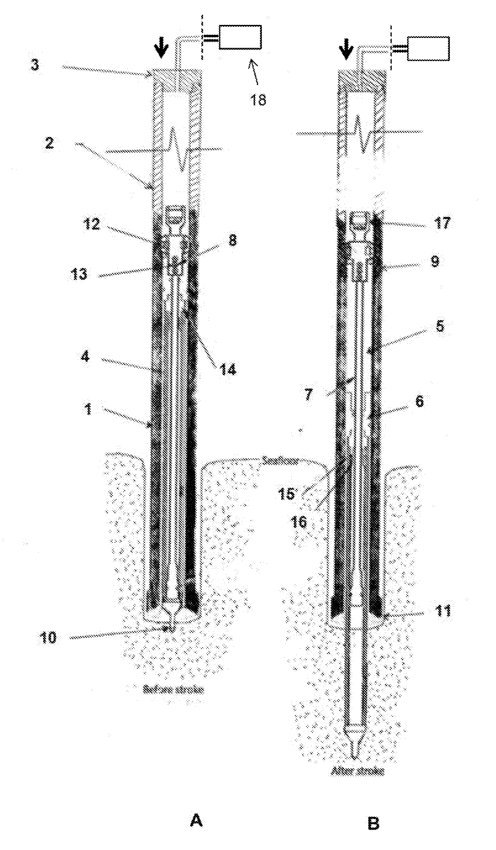
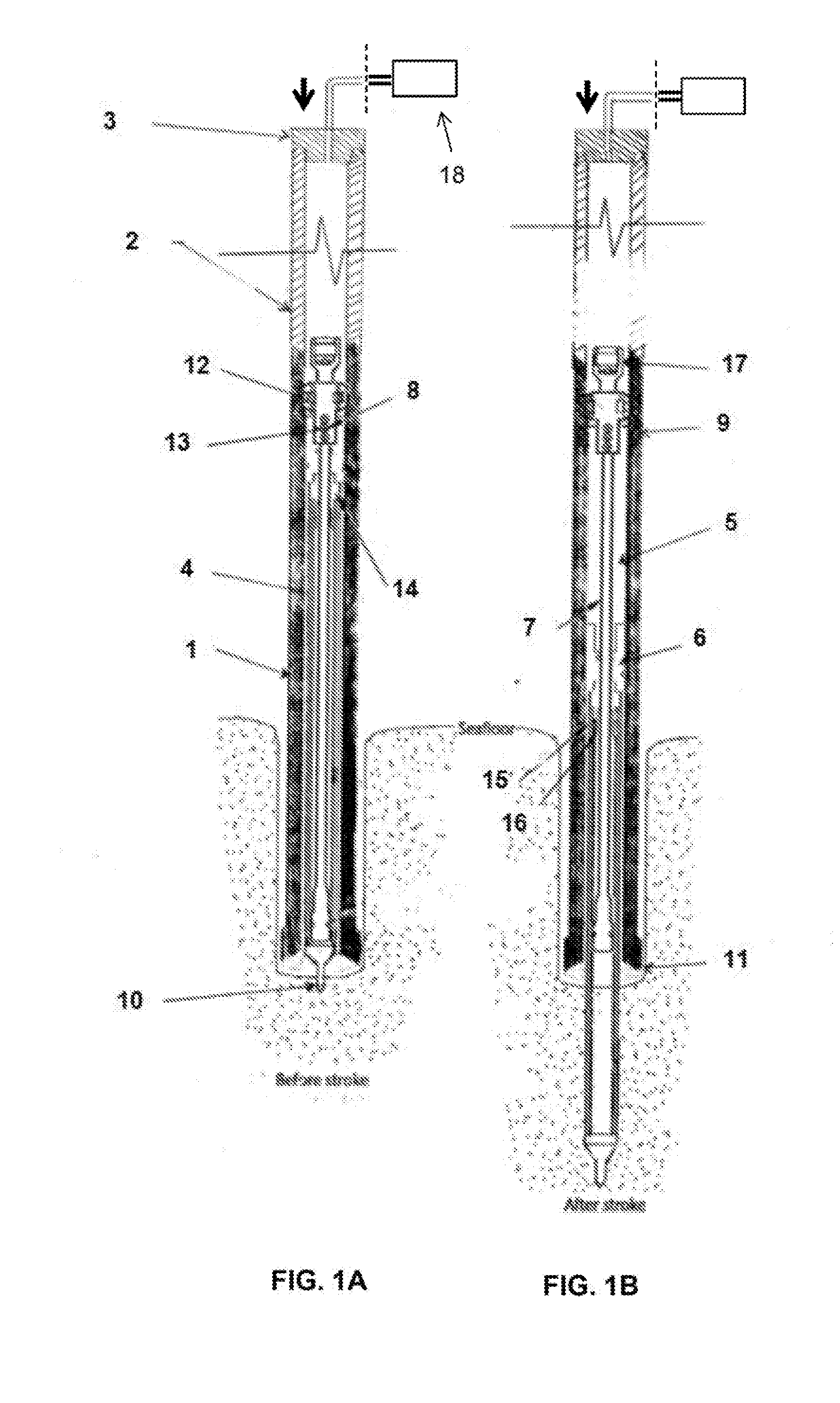
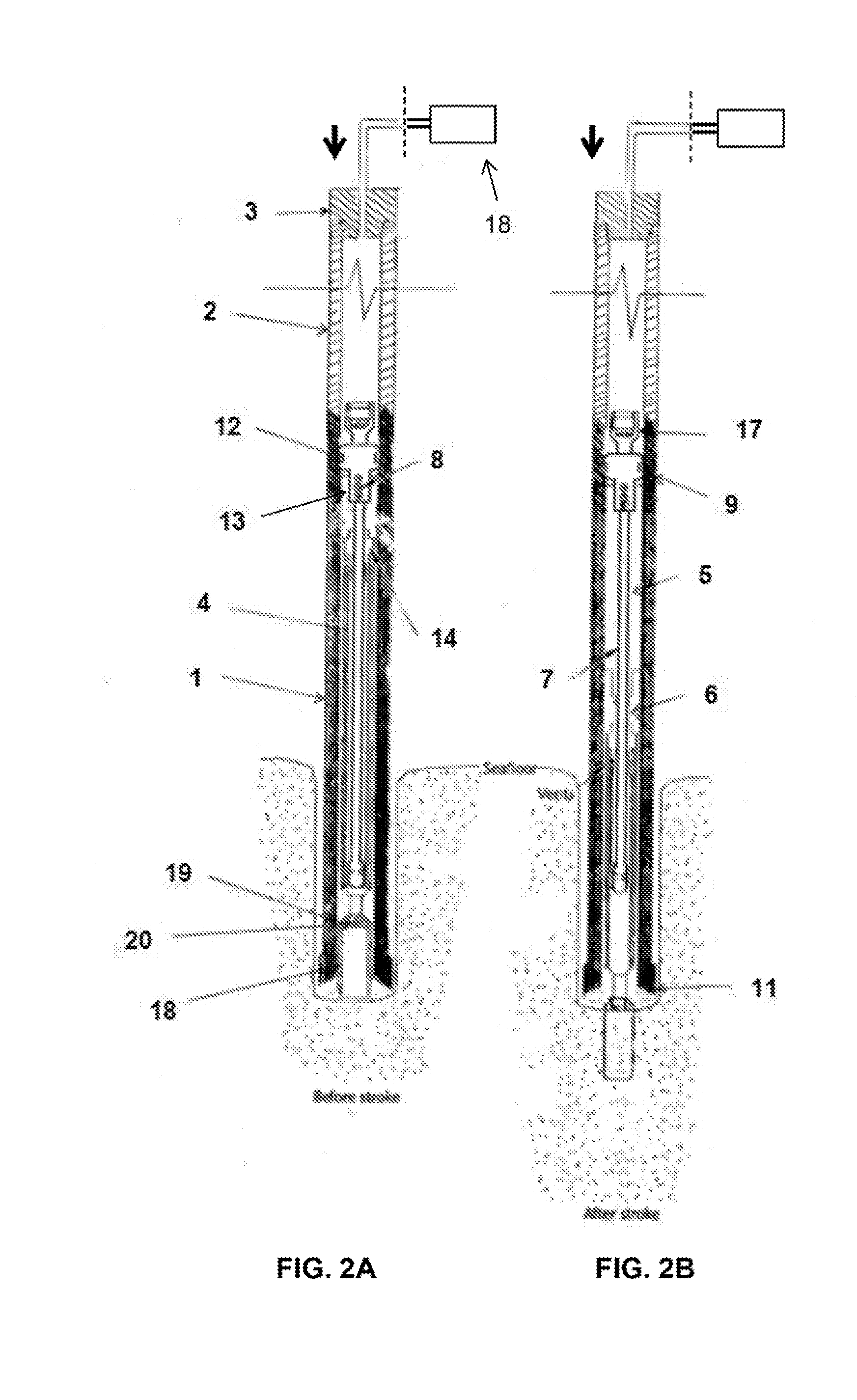
[0013]The present invention provides offshore dynamic delivery systems and methods for deploying geotechnical tools in an offshore environment. Certain testing tools take measurements (e.g., tip resistance, sleeve resistance, pore pressure, friction, etc.) in situ while soil samplers (e.g., piston sampler) collect soil samples that are analyzed above water. The geotechnical tools can be in situ testing probe...


PUM


Abstract

Offshore system for delivering geotechnical tools to seafloor is described. The system includes a carrier tube that includes an upper end and a lower end, wherein the carrier tube is characterized by an outer diameter and an inner diameter and wherein the inner diameter of the carrier tube defines a hydraulic cylinder; a landing sub shaped or installed at or near the upper end of the carrier tube, wherein inner diameter of the landing sub is smaller than the inner diameter of the carrier tube; a drill bit shaped or installed at or near the lower end of the carrier tube; an extension tube extending upward from the upper end of the carrier tube; an upward seal that seals top portion of the extension tubes; a compression system for introducing compressed fluid under the upward seal; a fixed rod that runs through the hydraulic cylinder; a hydraulic piston disposed in the hydraulic cylinder, wherein the hydraulic piston is moveable along the fixed rod; one or more shear pins configured to restrict displacement of the hydraulic piston until a sufficient fluid pressure is built up; and an inner tube disposed between the carrier tube and the hydraulic piston, wherein lower portion of the inner tube includes a cone penetrometer that is ballistically inserted into the soil during downward displacement of the hydraulic piston.

Description

PRIOR RELATED APPLICATIONS[0001]This application is a non-provisional application which claims benefit under 35 USC §119(e) to U.S. Provisional Application Ser. No. 62 / 193,414 filed Jul. 16, 2015, entitled “DOWNHOLE STINGER GEOTECHNICAL SAMPLING AND IN SITU TESTING TOOL,” which is incorporated herein in its entirety.FIELD OF THE DISCLOSURE[0002]The present invention generally relates to offshore geotechnical tools. More specifically, the present invention provides a system for ballistically inserting a geotechnical tool into a seafloor.BACKGROUND OF THE DISCLOSURE[0003]Geotechnical information of the seafloor is often needed for proper engineering design of structures such as fixed leg jacket structures, tension leg platforms, spread moorings, gravity based structures and pipelines. The cone penetrometer is an in situ testing tool that can be used to perform cone penetrometer test (“CPT”) to gather geotechnical engineering properties of seafloor. For most offshore applications, a la...

Claims


Application Information

Patent Timeline
Patent Type & Authority Applications(United States)
IPC IPC(8): E21B7/20E21B47/00E02D1/04E21B49/00E02D1/02E21B7/12E21B47/04
CPCE21B7/205E21B7/12E21B47/00E02D1/04E21B49/001E02D1/022E21B47/04
Inventor HOLLOWAY, GEORGE LEON
Owner CONOCOPHILLIPS CO
Why Eureka
Try Eureka