Speed change device

Active Publication Date: 2017-01-19
AISIN AW CO LTD +1
View PDF3 Cites 2 Cited by
  • Summary
  • Abstract
  • Description
  • Claims
  • Application Information

AI Technical Summary

Benefits of technology

[0016]Since the radially innermost position of the non-spline portion of the carrier is on the radially outer side of the radially outermost position of the spline engagement portion, there is caused no problem due to interference with the non-spline portion, and the spline engagement portion can be formed by broaching. Hence, productivity can be significantly improved compared to a case where it is necessary to perform shaping as in the re

Problems solved by technology

With such a configuration, the race abutment portion physically obstructs formation of a spline engagement portion for engagement with the tubular shaft member on the carrier, and broaching may not be applied.
Therefore, it is nece

Method used


Image

  • Speed change device
  • Speed change device
  • Speed change device

Examples


Example

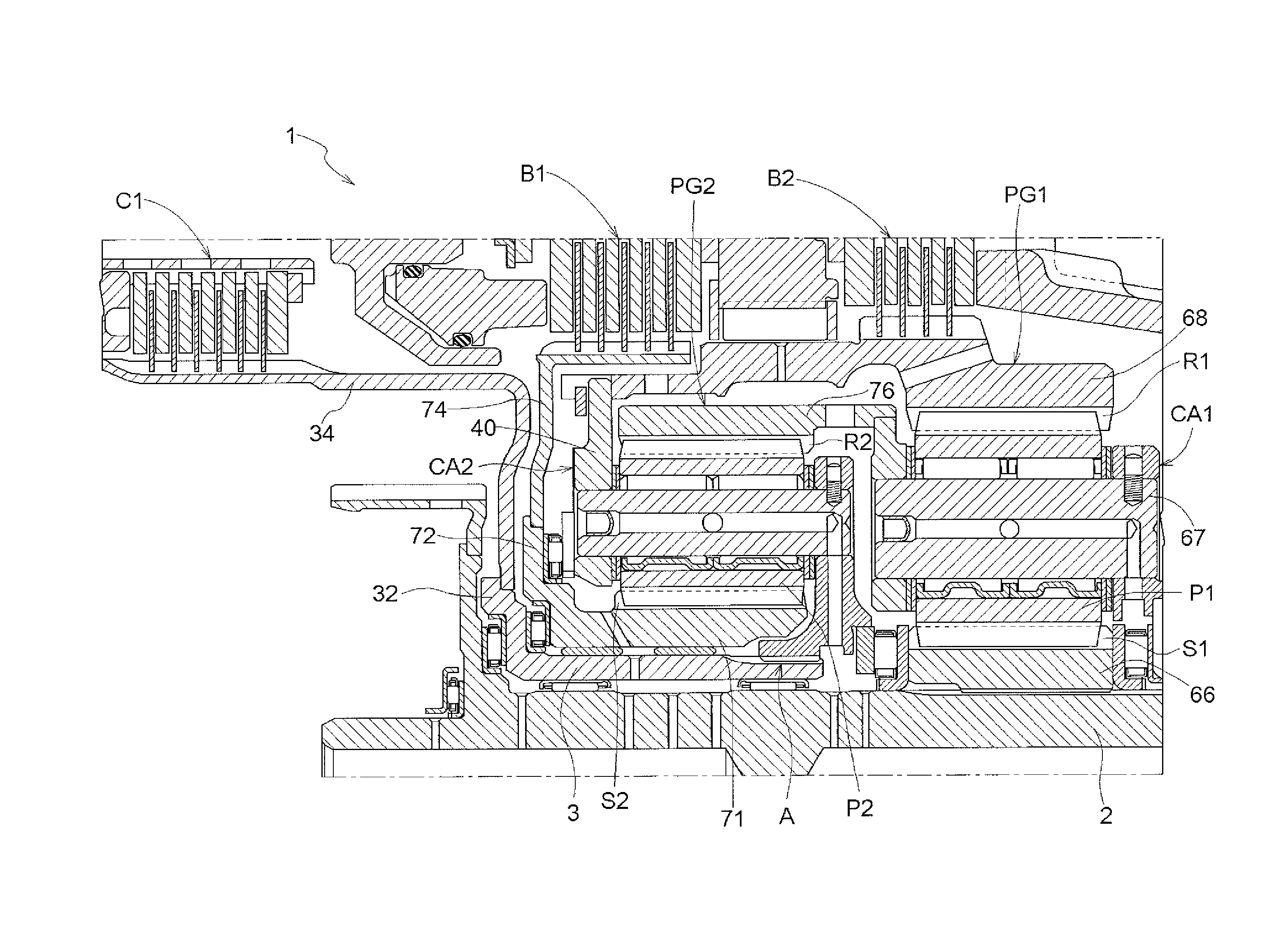
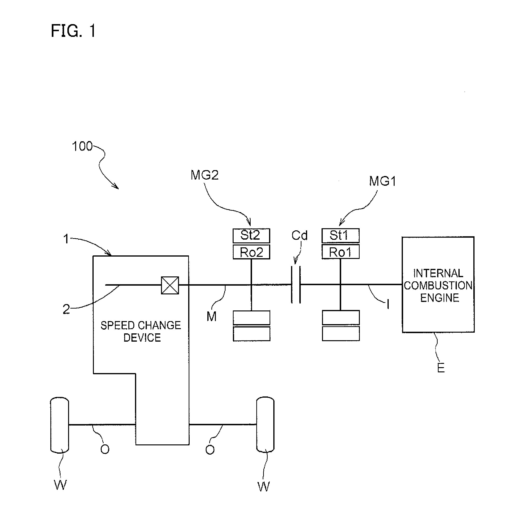
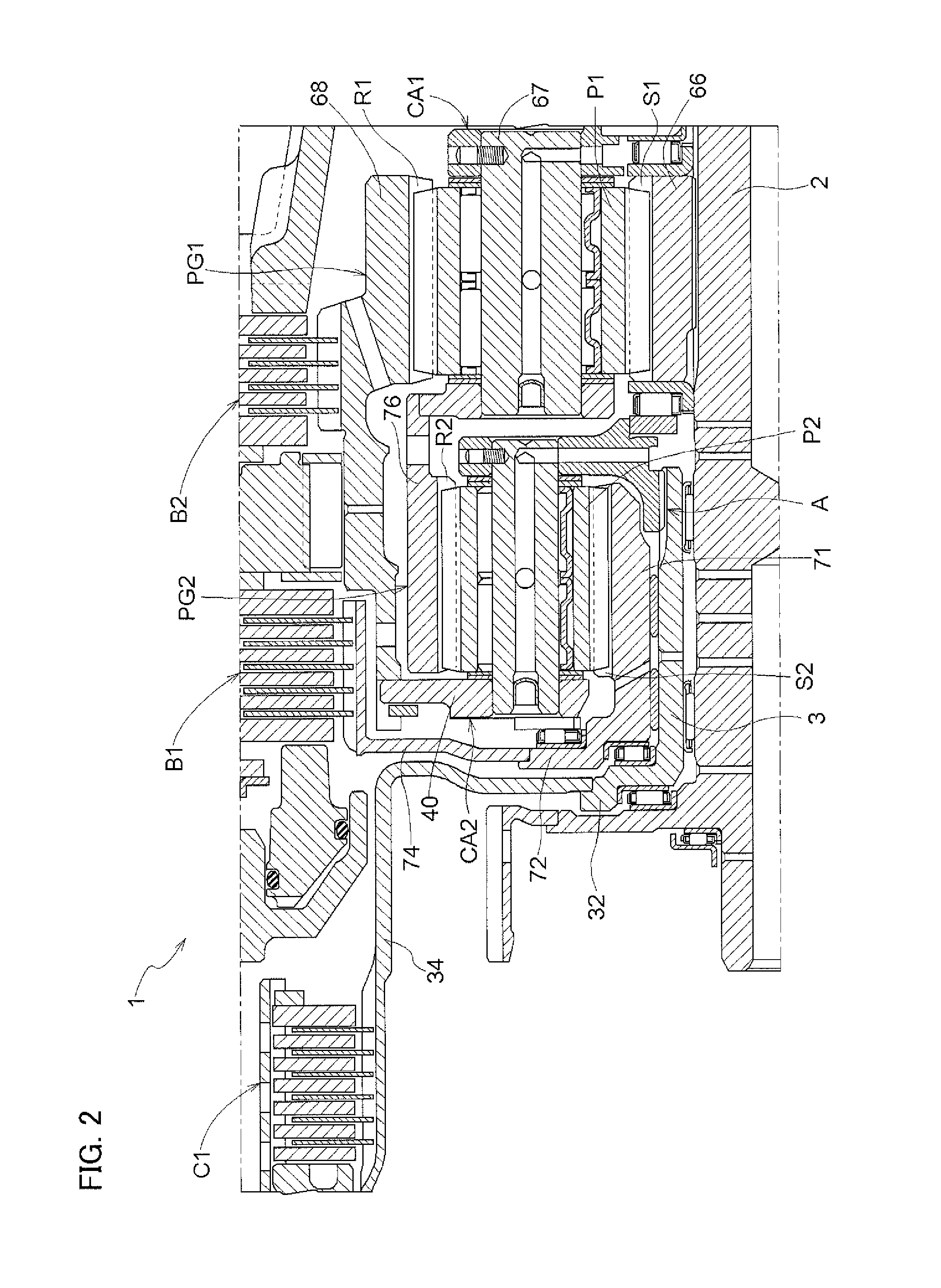
[0024]A speed change device according to an embodiment will be described with reference to the drawings. In the embodiment, a speed change device 1 is incorporated in a vehicle drive device 100. The vehicle drive device 100 according to the embodiment is a vehicle drive device (hybrid vehicle drive device) configured to drive a vehicle (hybrid vehicle) that includes both an internal combustion engine E and a rotary electric machine MG as drive force sources for wheels W of the vehicle. In the embodiment, the vehicle drive device 100 is constituted as a drive device for a two-motor series / parallel type hybrid vehicle.

[0025]The term “rotary electric machine MG” is used to comprehend a first rotary electric machine MG1 and a second rotary electric machine MG2. In addition, the term “rotary electric machine” includes any of a motor (electric motor), a generator (electric generator), and a motor generator that functions both as a motor and as a generator as necessary.

[0026]In the followi...


PUM


Abstract

A speed change device includes a power transfer shaft, a tubular shaft member, and a planetary gear mechanism that has a carrier. An in-shaft oil passage is formed in the power transfer shaft. A radially inner portion of the carrier and the tubular shaft member are splined to each other. An inside opening portion of a guide oil passage is formed in a non-spline portion of the radially inner portion. A target race member of a thrust bearing is disposed so as to abut against the carrier. The radially innermost position of the non-spline portion is on the radially outer side of the radially outermost position of a spline engagement portion. An oil receiving portion is formed by the tubular shaft member, the non-spline portion, and the target race member.

Description

I. TECHNICAL FIELD[0001]Embodiments of the present disclosure relate to a speed change device that includes a planetary gear mechanism that has a carrier.BACKGROUND ART[0002]A device described in Japanese Patent Application Publication No. 2007-270865 (JP 2007-270865 A) (Patent Document 1) is known as an example of the speed change device described above. The structure disclosed in Patent Document 1 will be described below with reference to FIG. 6 of the present application which is a reprint of FIG. 3 of Patent Document 1. As illustrated in FIG. 6, the speed change device according to Patent Document 1 includes a planetary gear mechanism disposed coaxially with a power transfer shaft, and the planetary gear mechanism includes a carrier that rotatably supports a pinion. The speed change device includes a structure for leading oil supplied through the inside of the power transfer shaft to a carrier shaft to lubricate a support portion of the carrier shaft for the pinion. An oil recei...

Claims


Application Information

Patent Timeline
IPC IPC(8): F16H57/04F16H57/00F16D1/06F16H57/08
CPCF16H57/0484F16H57/082F16H57/043F16H57/0479F16H57/0025F16D1/06Y10S903/945B60K6/547B60K6/442B60Y2200/92B60Y2400/73B60Y2306/03B60K6/365F16H57/08F16H57/04F16H57/0426F16H57/0471
Inventor MIYOSHI, KATSUNORISASAKI, KENJIOMURO, KEISUKEOKUDA, KOICHIYAMAMOTO, MASAFUMIIMAI, KEITA
Owner AISIN AW CO LTD
Why Eureka
Try Eureka