Sensor device for a motor vehicle

US20170018844A1Active Publication Date: 2017-01-19ROBERT BOSCH GMBH
2 Cites 2 Cited by

Patent Information

Authority / Receiving Office
US · United States
Current Assignee / Owner
Publication Date
2017-01-19

Smart Images

  • Figure 1
    Figure 1
  • Figure 2
    Figure 2
  • Figure 3
    Figure 3
Patent Text Reader

Abstract

A sensor device for a motor vehicle, including a first transmitting antenna, which is situated on a surface of a substrate, has a narrow lobe-type directional characteristic and includes a defined number of planar antenna elements; a second transmitting antenna situated on the surface of the substrate has a wide lobe-type directional characteristic, including a defined number of planar antenna elements, the directional characteristics of the two transmitting antennas being oriented opposite one another by a defined angle, with respect to a boresight; and at least one receiving antenna situated on the surface of the substrate including a defined number of planar antenna elements.
Need to check novelty before this filing date? Find Prior Art

Description

CROSS REFERENCE

[0001] The present application claims the benefit under 35 U.S.C. §119 of German Patent Application No. DE 102015213553.5 filed on Jul. 17, 2015, which is expressly incorporated herein by reference in its entirety.FIELD

[0002] The present invention relates to a sensor device for a motor vehicle. The present invention also relates to a method for manufacturing a sensor device for a motor vehicle.BACKGROUND INFORMATION

[0003] Radar sensors in a frequency band from approximately 76 GHz to approximately 77 GHz are being used to an increasing extent in systems for detection of surroundings, in particular in motor vehicles which have modern driver assistance systems. Conventional sensor generations are used for the long-distance range (detection range up to approximately 250 m) including strongly focusing systems, the detected objects being detected only in a narrow angle range, for example, less than approximately ±30° with respect to the vehicle axis.

[0004] A plurality of novel...

Examples

Embodiment Construction

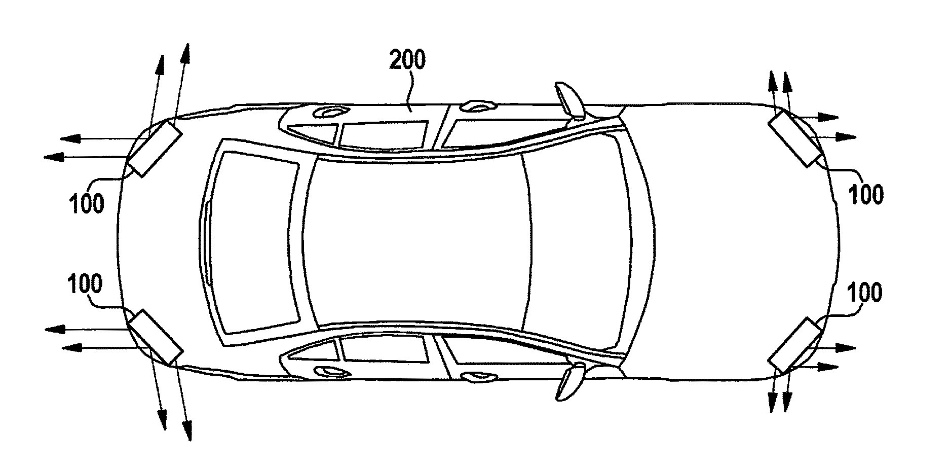
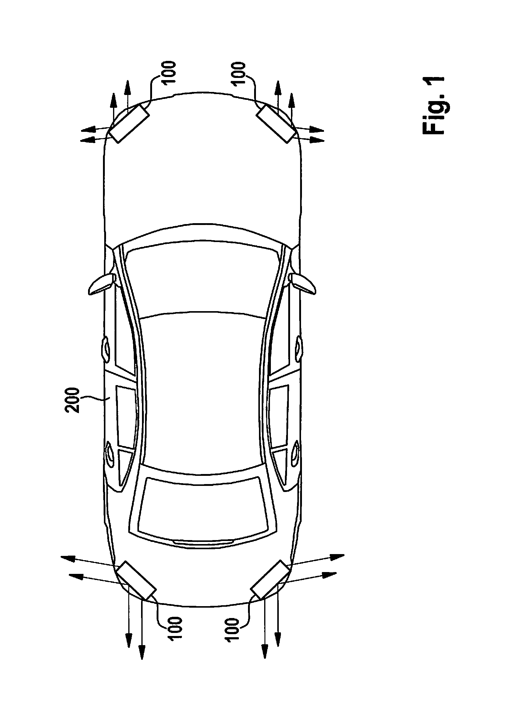
[0028]FIG. 1 shows, in a top view, a motor vehicle 200 including multiple sensor devices 100, each sensor device 100 being situated in one of the four outer corners of the motor vehicle. A forward-sensing front sensor device is not shown. Sensor devices 100 are designed as radar sensors and are provided to focus a transmission / receiving power from transmitting antennas TX and receiving antennas RX, where defined sensing ranges are implemented in a defined field of view.

[0029]All antennas TX, RX have a defined number of rectangular or square planar antenna elements 12, which are situated on a substrate 10 (not shown) and implement generally conventional “patch antennas” in this way.

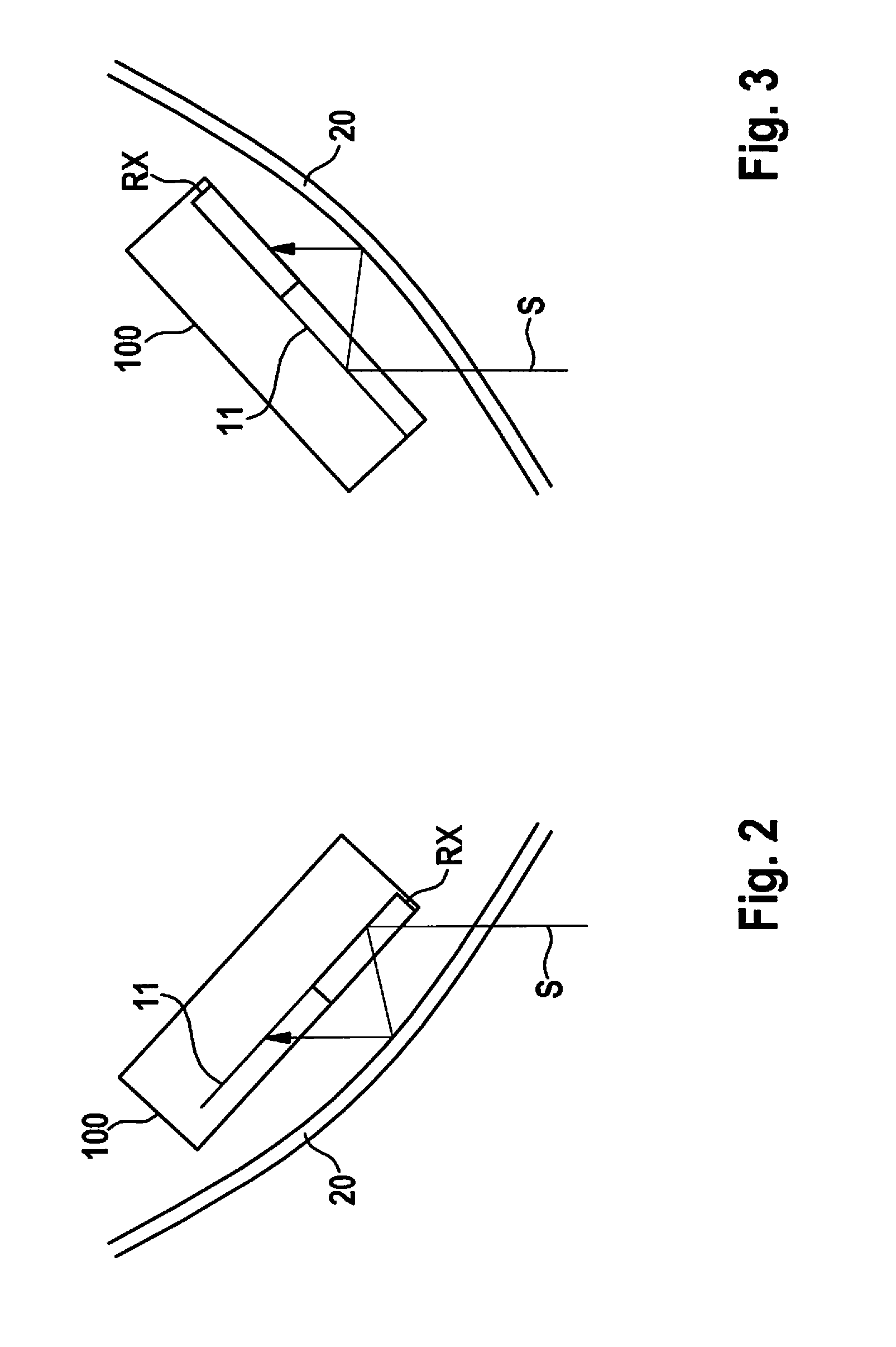
[0030]FIG. 2 schematically shows a traditional sensor device 100 installed behind a bumper 20 in a left rear corner of motor vehicle 200. It is apparent that a reception beam S coming in externally initially strikes receiving antenna RX. In a further sequence, reflections of reception beam S occur between ...