
Wedge spring clip mounting system for photovoltaic modules

Active Publication Date: 2017-01-19
TESLA INC
View PDF18 Cites 0 Cited by
  • Summary
  • Abstract
  • Description
  • Claims
  • Application Information

AI Technical Summary

Benefits of technology

The invention is a photovoltaic mounting system that includes a base portion, a clamp, and a support beam. The clamp has a spring base and a pair of clamping flanges that extend upwardly from the spring base. The support beam is designed to fit between the clamping flanges and resiliently deform the spring base to lock it into the base portion. The system also includes a photovoltaic module coupling device that can be mechanically coupled to the frames of at least two photovoltaic modules. The technical effects of the invention include improved stability and secure mounting of photovoltaic modules on various structures, such as roofs and buildings.

Problems solved by technology

Although effective, these traditional systems required complex and time-consuming installations and utilized relatively large amount of materials.
Although effective at reducing water leaks and covering missed drill holes, flashings can increase the time of installation because when they are used, the installer must complete all site preparation first before placing any of the PV modules, installing a flashing at each intended roof penetration.
This bottleneck prevents an installer from installing the array row-by-row or panel-by-panel and, as a result, may slow-down the rate at which PV can be installed, may require larger installation crews, or both.
Each time an existing roofing nail is removed, a new potential leak point is created.
Finally, each flashing adds a material cost to each solar installation that becomes significant when multiplied against every roof penetration of every installed array.

Method used


Image

  • Wedge spring clip mounting system for photovoltaic modules
  • Wedge spring clip mounting system for photovoltaic modules
  • Wedge spring clip mounting system for photovoltaic modules

Examples


Embodiment Construction

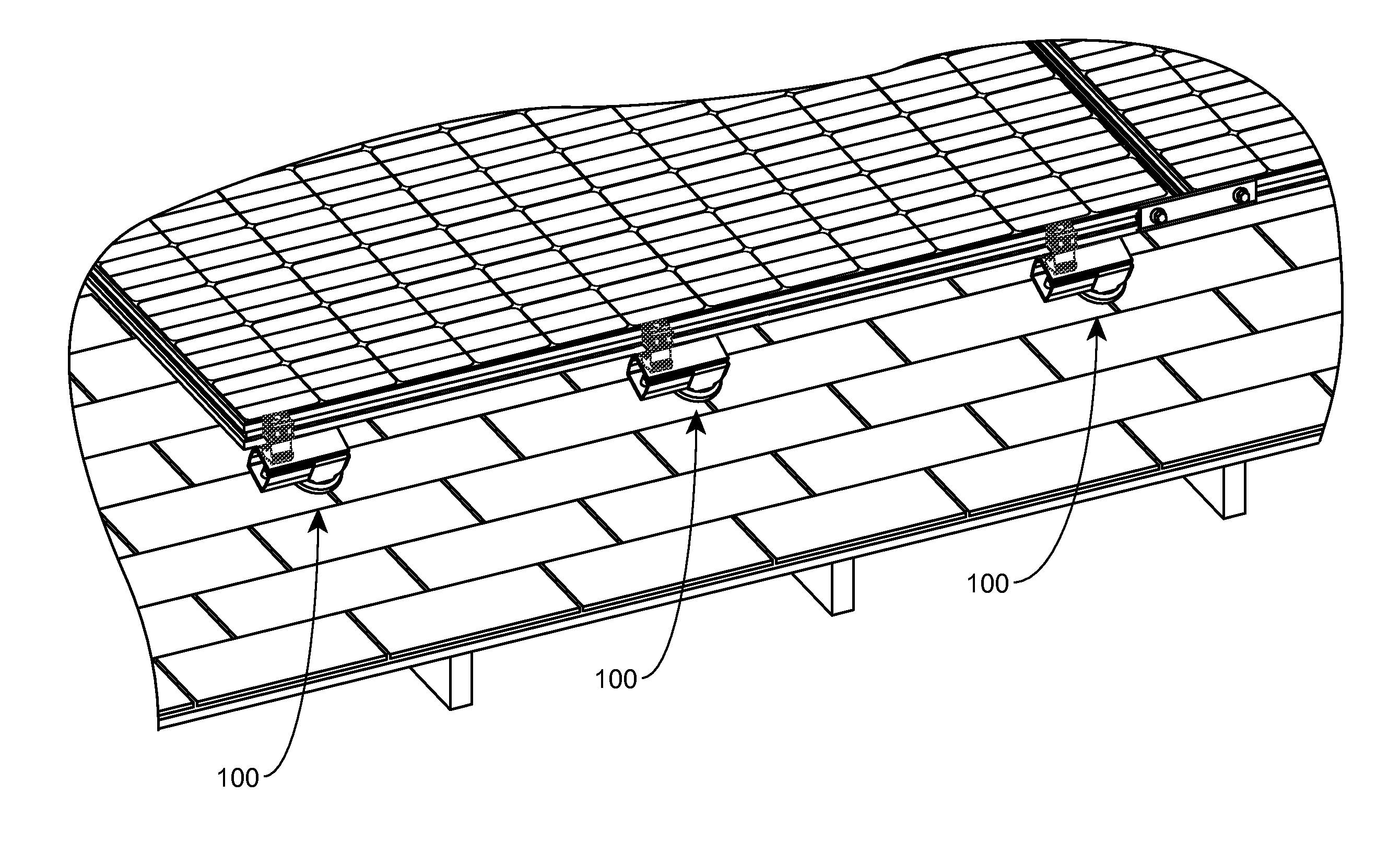
[0035]Embodiments of the invention are generally directed towards a system for mounting a PV module to a support structure such as a roof surface. The system can include a base portion and a clamp assembly for supporting a PV module. The clamp assembly may include a spring clamp that when resiliently actuated with the base portion assembly, provides a boltless system for rigidly fixing the clamp assembly to the base portion in a sufficient manner to support the weight of one or more PV modules. Advantageously, such a system requires little to no tools for installation, and hence installation time is greatly reduced over prior systems that require additional tools and bolting. The following description details some examples of such a system.

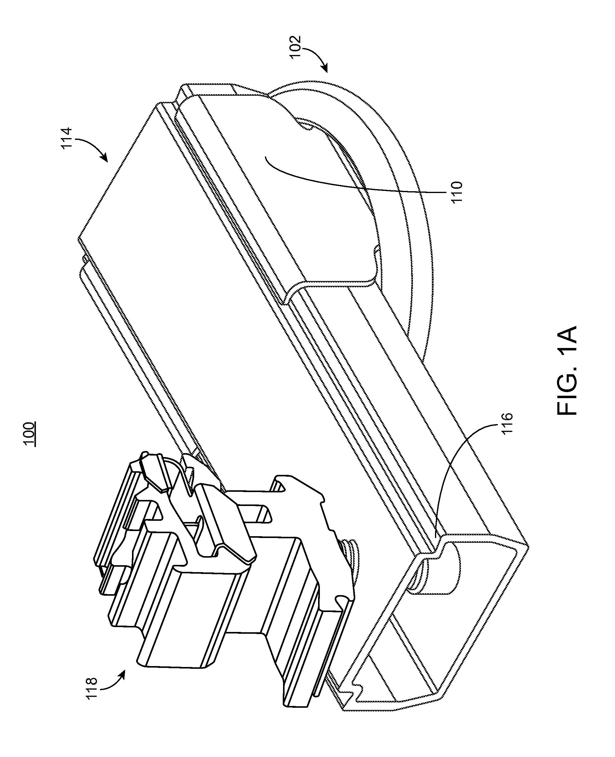
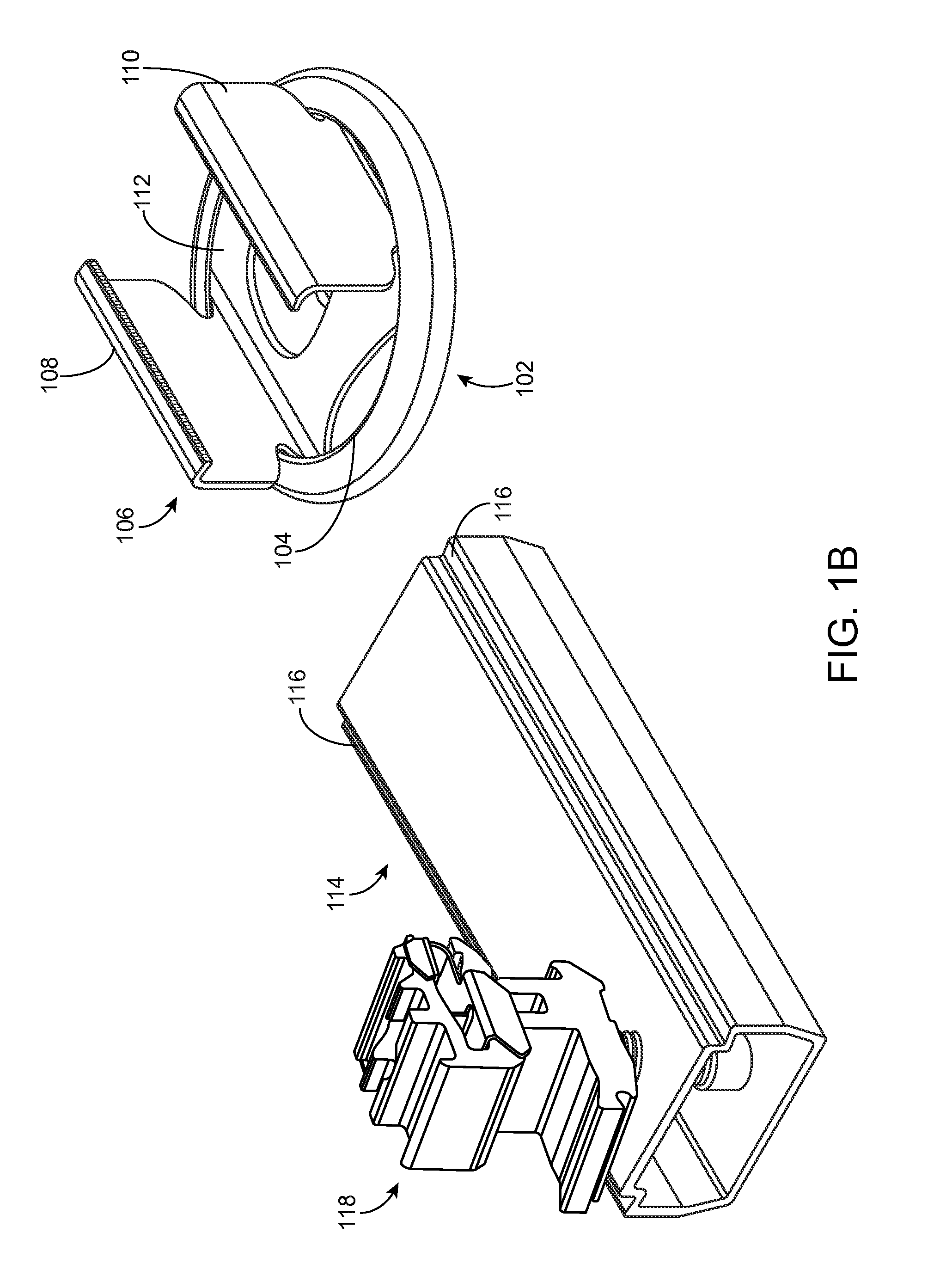
[0036]FIGS. 1A and 1B show perspective views of an exemplary system 100 for mounting a PV module to a structure, such as a roof. System 100 includes base portion 102, which here is formed as a puck having lip 104 that can curve inwardly. Base port...


PUM


Abstract

A photovoltaic (PV) mounting system having a base portion that is substantially planar and having a first roof-facing side and an opposite module-facing side. The base portion has a lip that circumscribes the perimeter of the base portion and curves inward on the module-facing side. A clamp having a spring base is partially installed in the base portion and has a pair of clamping flanges extending upwardly from the base portion. A support beam comprising a pair of ledges adapted to mate with the clamping flanges of the clamp and a bottom portion that is supported by the spring base. A PV module coupling device is mechanically coupled to the support beam and configured for coupling to the frames of at least two photovoltaic modules.

Description

CROSS REFERENCE TO RELATED APPLICATIONS[0001]This application is related to co-assigned and co-invented U.S. patent application Ser. No. ______ (Attorney Docket No. P133-1NUS), entitled “Clamp and Bowel Mounting System for Photovoltaic Modules, filed on Jul. 15, 2015, which is incorporated by reference herein.BACKGROUND OF THE INVENTION[0002]There are many systems available for mounting photovoltaic (PV) modules to building structures, such as a roof. These systems serve as a rigid interconnection element between a roof and a PV module to hold the modules in place and resist the forces of gravity and wind.[0003]Traditionally, mounting systems consisted of rows of rail structures attached to the roof in columns or rows. Module clamps were used to attach the PV modules to these rail structures. Although effective, these traditional systems required complex and time-consuming installations and utilized relatively large amount of materials. Eventually, pioneers in the solar industry, su...

Claims


Application Information

Patent Timeline
IPC IPC(8): H02S20/23
CPCH02S20/23F24S25/61F24S2025/6004F24S2025/801Y02B10/10Y02B10/20Y02E10/47Y02E10/50
Inventor ALMY, CHARLESHUDSON, TYRUSMOLINA, DAVID
Owner TESLA INC
Learn More