Easel with a built-in Connecting Device for a Mounting Mechanism

a technology of mounting mechanism and connecting device, which is applied in the field of easels, can solve the problems of complicated solution of the lourida, and achieve the effects of reducing the price of the product, enabling the user to save cost and space, and saving the cost of parts production

Inactive Publication Date: 2017-01-26
SELWA ROBERT ALLEN
View PDF1 Cites 3 Cited by
  • Summary
  • Abstract
  • Description
  • Claims
  • Application Information

AI Technical Summary

Benefits of technology

[0004]This embodiment features an easel arm, or arms, that attaches directly to a camera tripod-like mounting mechanism using an embedded connecting device and optional drill hole for a mount nipple(s) or guide. This empowers the user to cost and space savings, along with adding the tripod-like features to the easel. The easel allows for the work piece to be secured to the tripod, and be manipulated for height adjustment—to tilt, be rotated, and / or swivel according to the capabilities of the tripod. Now the easel performs more than just a resting place for the work piece. The marriage of the easel and tripod functions allow for a new hybrid unit to be created. This embodiment now affords more utility and value to the owner.
[0005]The advantage of this embodiment over prior art is the simplicity of directly attaching to the camera tripod mount and forgoing the perceived need for an intermediary carriage bracket interface as taught by Louridas—U.S. Pat. No. 5,791,623. There is a significant improvement in this embodiment that saves on the cost to manufacture the parts, and thus lowers the price of the product, and also eliminates having extra parts that could break down.

Problems solved by technology

I found that Louridas' solution was too complicated.

Method used


Image

  • Easel with a built-in Connecting Device for a Mounting Mechanism
  • Easel with a built-in Connecting Device for a Mounting Mechanism
  • Easel with a built-in Connecting Device for a Mounting Mechanism

Examples


first embodiment

Operation of First Embodiment

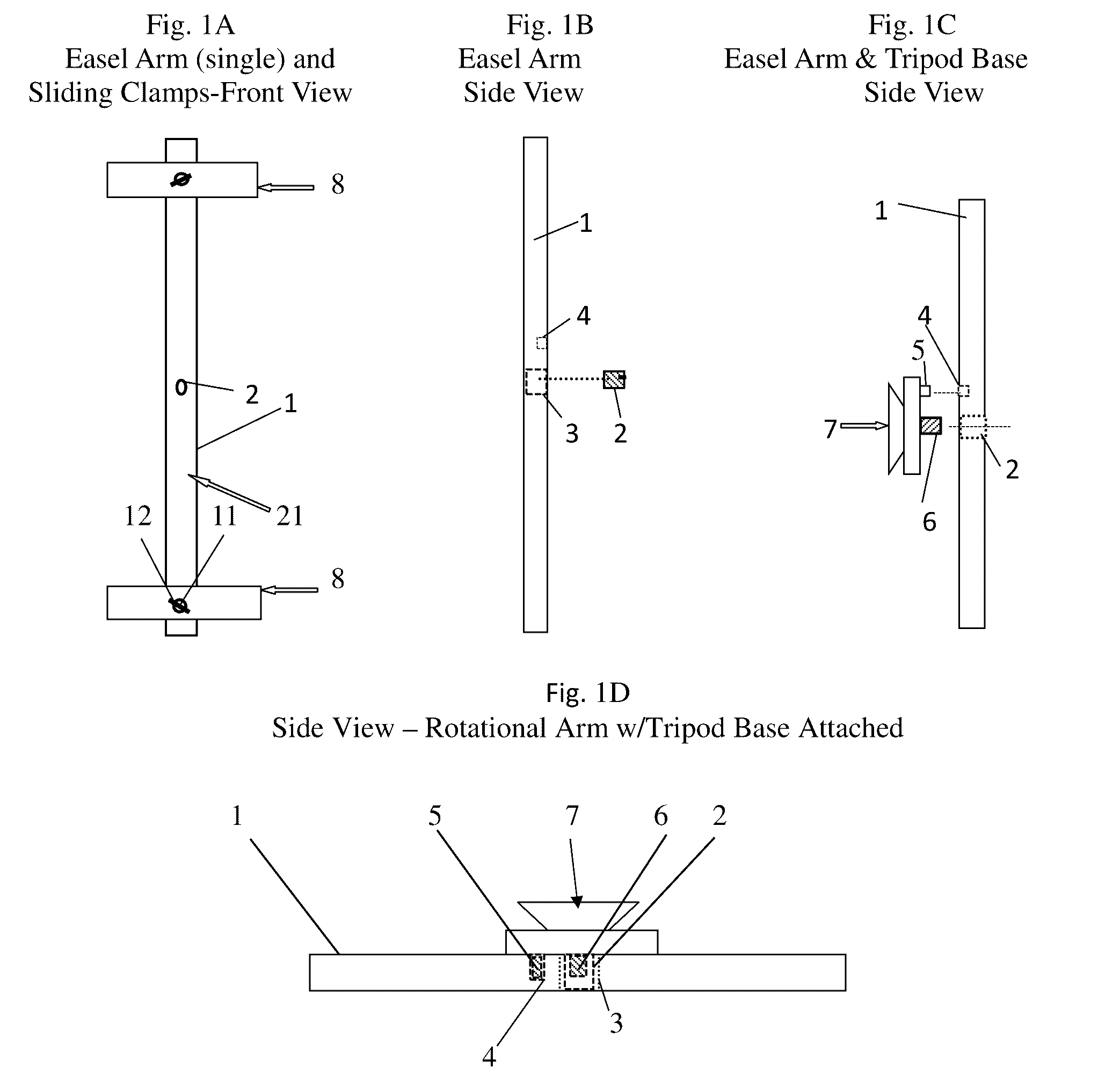
FIGS. 1A-1D, &2A-2C, &3A-3D—Single Easel Arm with Threaded Insert

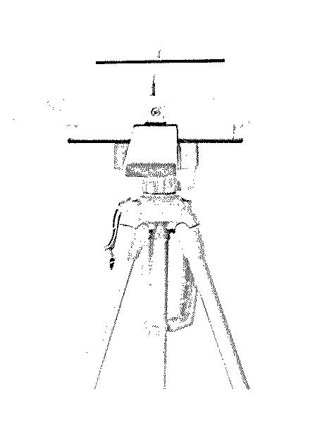
[0048]The easel arm (1) attaches and is mated and secured to the camera mount (or other similar mating mechanism) (7) by screwing the mounting screw (6) into the inner threads of the threaded insert (2) in the easel arm (1). If there is a stabilizing nipple(s) (5) on the camera mount (7), this is lined up and inserted into the hole (4) on the easel arm (1) to keep the mounted easel more secure.

[0049]The sliding bar clamps pictured here (8) slide on or over the easel arms (1) and are secured to the arm (1) with the thumb screws (12). The canvas (15) is secured onto the easel (1) by being sandwiched (FIG. 3A) between the sliding bar clamps (8). The secured canvas (15) can then be maneuvered and positioned being limited to the functions afforded by the camera tripod (13) to benefit the user.

Description of the Second Embodiment

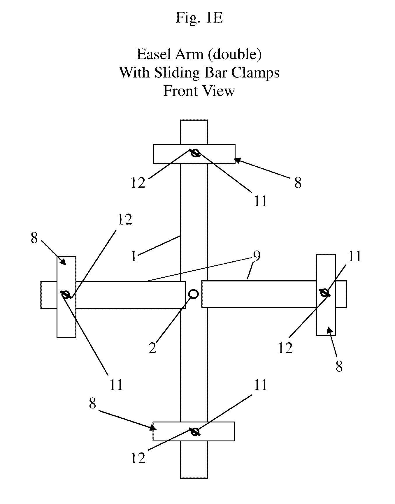
FIG. 1E—Double Easel Arm w / Threaded Insert

[0050]In FIG. 1E we have ...

second embodiment

Operation of Second Embodiment

FIGS. 1E—Double Easel Arm with Threaded Insert

[0051]The mounting mechanism (7) is screwed into the connecting device (2) in the easel arm (1) and re-attached to the tripod (13). The canvas (15) is now secured by the sliding bar clamps (8) on all four sides instead of just two in the single arm embodiment.

Description of Alternative Embodiments

FIGS. 4A &4B—Wall Mount and Telescoping Arm

[0052]FIG. 4A is an example of how the easel arm (1) can be attached to a mounting mechanism (7) and camera mount head (14) which is also attached to a wall mount (18) instead of a camera tripod (13) and allows the artist or presenter the ability to rotate and tilt his work piece while being mounted on a wall. This saves space in the artist's studio, or gives a presenter an option for displays. The wall mount could be stationary or be equipped with a sliding mechanism to adjust the height.

[0053]FIG. 4B shows how the easel arm (1) with the embedded connecting device (2) can ...


PUM


Abstract

A way to convert a camera tripod into an artist easel. The easel consists of a one or two arm design employing a built-in adapter, or connecting device in the center of the arm(s) of the attaching easel whereby the easel arm attaches directly to the mounting device of the tripod by way of the connecting device, allowing the tripod features to be extended to the easel. Attributes such as the tilting, raising, and rotating features of the tripod are then incorporated and translated as new easel functions.

Description

CROSS-REFERENCE TO RELATED APPLICATIONS[0001]This application claims the benefit of provisional application Ser. No. 62 / 195,550, filed Jul. 22, 2015 by the present inventor.BACKGROUNDField[0002]This application relates to an easel, specifically artist and display easels.Background of the Invention[0003]U.S. Pat. No. 5,791,623—granted to Michael C. Louridas on Aug. 11, 1998 performs the same function of combining, adapting, and connecting an easel to a camera tripod as this embodiment. I found that Louridas' solution was too complicated. This embodiment is much simpler and eliminates the need for a middle carriage bracket to interface between the camera tripod and easel arm.SUMMARY OF THE EMBODIMENT[0004]This embodiment features an easel arm, or arms, that attaches directly to a camera tripod-like mounting mechanism using an embedded connecting device and optional drill hole for a mount nipple(s) or guide. This empowers the user to cost and space savings, along with adding the tripod...

Claims


Application Information

Patent Timeline
Patent Type & Authority Applications(United States)
IPC IPC(8): A47B97/04A47B97/00F16M11/14F16M11/24F16M11/26F16M13/02F16M11/16F16B2/12A47B83/00F16M11/20
CPCA47B97/04A47B83/00A47B97/001F16M11/14F16M11/2078F16M2200/068F16M13/02F16M11/16F16B2/12F16M11/242F16M11/26F16M11/04
Inventor SELWA, ROBERT ALLEN
Owner SELWA ROBERT ALLEN
Why Eureka
Try Eureka