
Apparatus and methods for detection of objects using broadband signals

a technology of object detection and broadband signal, applied in the field of remote detection of objects, can solve the problems of inability to detect obstacles between pulses, two traditional sonars operating at the same frequency band at the same time may not function correctly, and existing ranging technologies are susceptible to interfering with one another

Active Publication Date: 2017-01-26
BRAIN CORP
View PDF1 Cites 56 Cited by
  • Summary
  • Abstract
  • Description
  • Claims
  • Application Information

AI Technical Summary

Benefits of technology

The present patent provides apparatus and methods for detecting objects using reverse correlation ranging. The apparatus includes a transmitter component that transmits a broadband signal, a receiver component that samples the reflected signal, and computerized logic. The computerized logic obtains a modified instance of the transmitted signal, performs a comparison of the modified signal to the sampled signal, and evaluates the comparison to a detection criterion to determine the positional attribute of the object. The technical effects of this patent include improved object detection and range estimation using reverse correlation ranging, as well as improved accuracy and efficiency in identifying the positional attributes of objects.

Problems solved by technology

Some existing ranging technologies may be susceptible to interfere with one another.
For example, two traditional sonars operating at the same time at in the same frequency band may not function correctly due to cross interference.
Additional deficiencies are that existing ranging technologies are often pulsed, as in not operated continuously in time, and as such detection of obstacles between pulses is not possible.
Further, existing technologies normally are narrow band, and as such some objects are not detectable at a specific frequency but would be detected using broad band transmissions.

Method used


Image

  • Apparatus and methods for detection of objects using broadband signals
  • Apparatus and methods for detection of objects using broadband signals
  • Apparatus and methods for detection of objects using broadband signals

Examples


Embodiment Construction

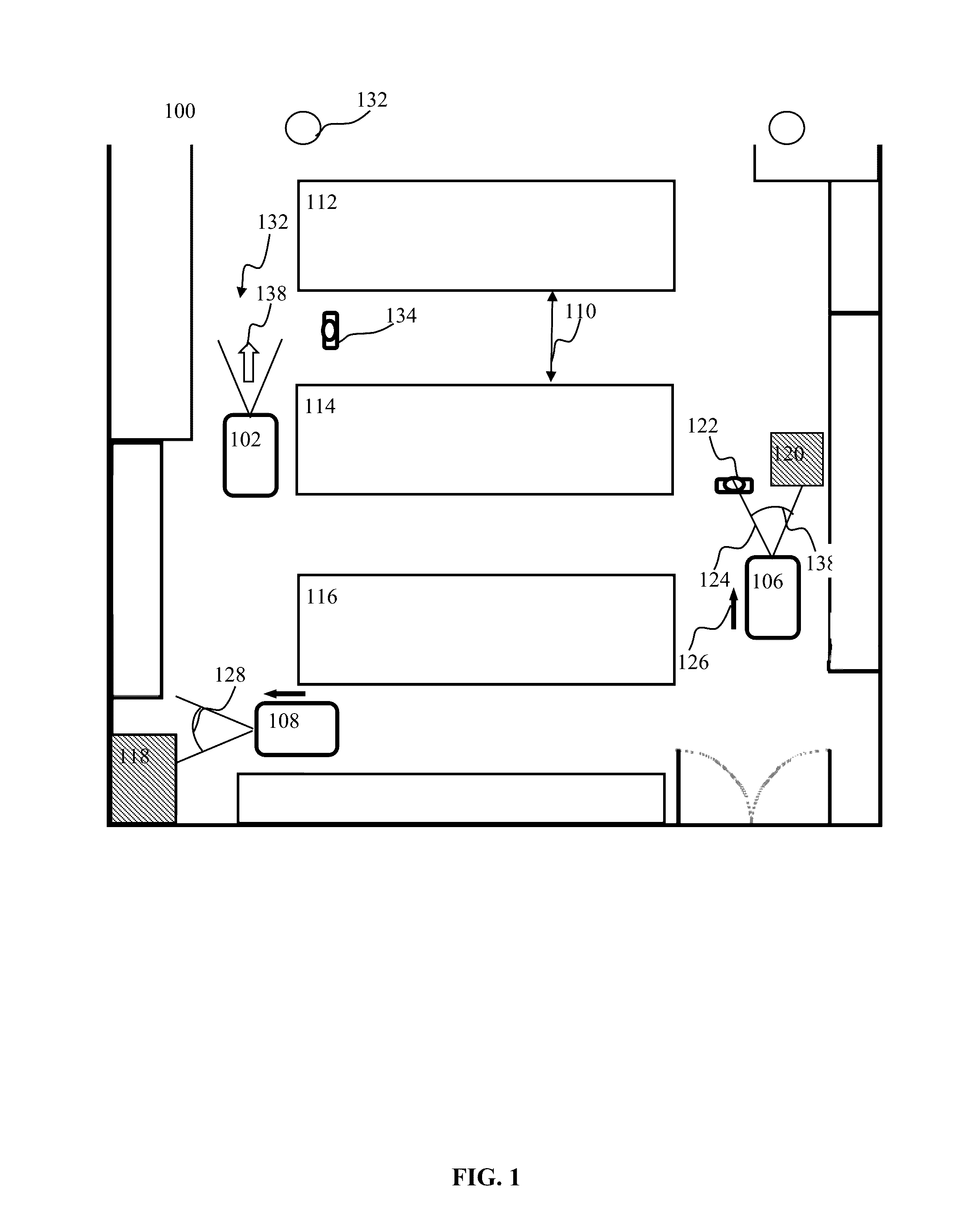
[0032]Embodiments of the present disclosure will now be described in detail with reference to the drawings, which are provided as illustrative examples so as to enable those skilled in the art to practice the disclosure. Notably, the figures and examples below are not meant to limit the scope of the present disclosure to a single embodiment, but other embodiments are possible by way of interchange of or combination with some or all of the described or illustrated elements. Wherever convenient, the same reference numbers will be used throughout the drawings to refer to same or like parts.

[0033]Where certain elements of these embodiments can be partially or fully implemented using known components, only those portions of such known components that are necessary for an understanding of the present disclosure will be described, and detailed descriptions of other portions of such known components will be omitted so as not to obscure the disclosure.

[0034]In the present specification, an e...


PUM


Abstract

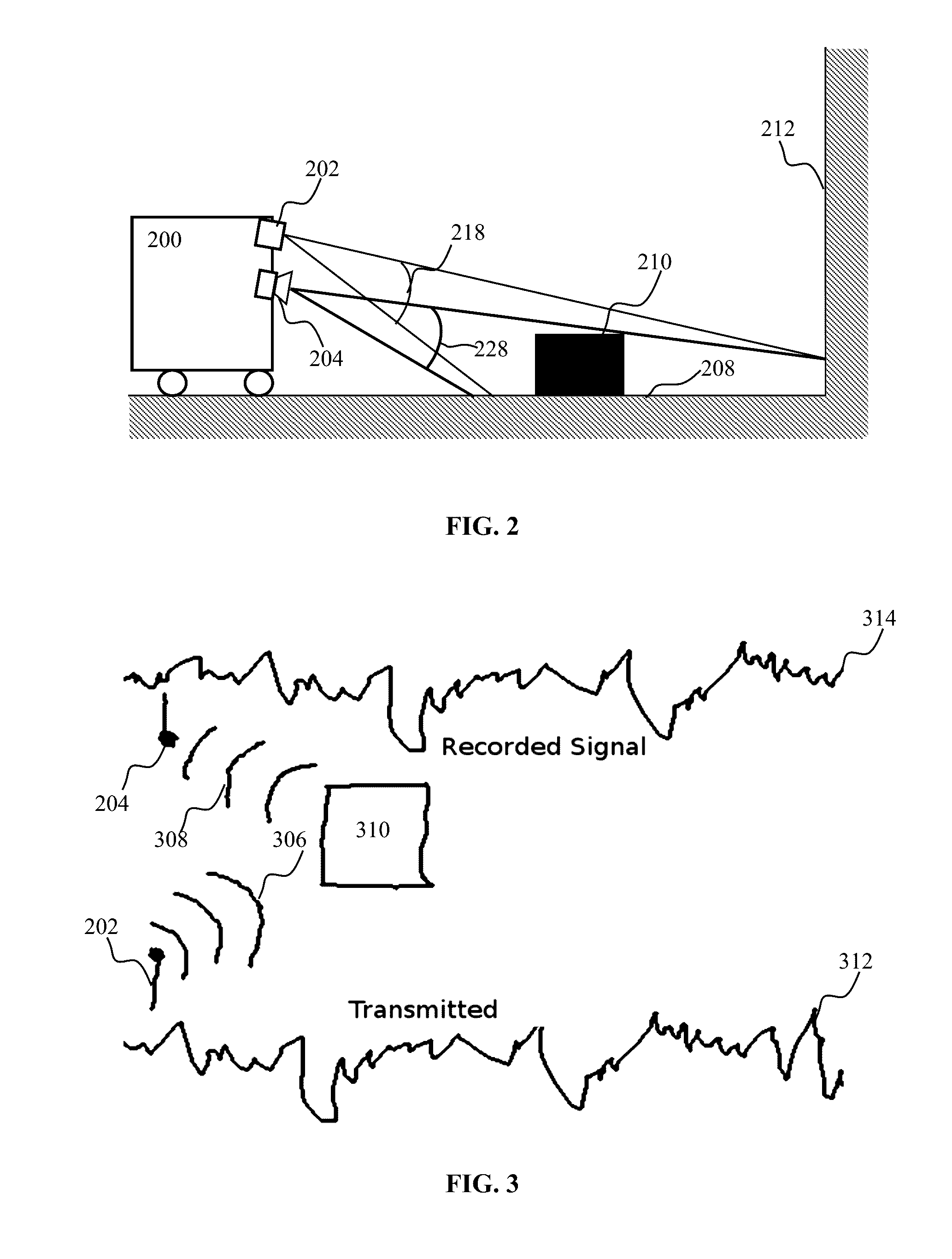
Broadband signal transmissions may be used for object detection and / or ranging. Broadband transmissions may comprise a pseudo-random bit sequence or a bit sequence produced using, a random process. The sequence may be used to modulate transmissions of a given wave type. Various types of waves may be utilized, pressure, light, and radio waves. Waves reflected by objects within the sensing volume may be sampled. The received signal may be convolved with a time-reversed copy of the transmitted random sequence to produce a correlogram. The correlogram may be analyzed to determine range to objects. The analysis may comprise determination of one or more peaks / troughs in the correlogram. Range to an object may be determines based on a time lag of a respective peak.

Description

COPYRIGHT[0001]A portion of the disclosure of this patent document contains material that is subject to copyright protection. The copyright owner has no objection to the facsimile reproduction by anyone of the patent document or the patent disclosure, as it appears in the Patent and Trademark Office patent files or records, but otherwise reserves all copyright rights whatsoever.BACKGROUND OF THE DISCLOSURE[0002]Field of the Disclosure[0003]The present disclosure relates generally to remote detection of objects and more particularly in one exemplary aspect to computer apparatus and methods for detecting objects using reverse correlation ranging.[0004]Description of Related Art[0005]Object detection may be of use in a variety of applications including assisted vehicle navigation, autonomous robotic navigation, home automation, classification, and / or other applications. In some applications of robotic navigation it may be of benefit to detect objects remotely with a given margin of tim...

Claims


Application Information

Patent Timeline
Patent Type & Authority Applications(United States)
IPC IPC(8): G01S7/02G01S13/08G01S15/08G01S17/08G01S7/486G01S7/4865G01S13/931G01S15/931G01S17/32G01S17/931
CPCG01S7/02G01S17/08G01S13/08G01S15/08G01S7/4865G01S15/931G01S17/003G01S13/003G01S13/0209G01S13/931G01S15/003G01S17/32G01S7/023G01S7/354G01S7/493G01S7/536G01S13/325G01S15/325G01S17/931G01S7/0234
Inventor RICHERT, MICAH
Owner BRAIN CORP
Learn More