Raid hot spare system and method

a spare system and hot spare technology, applied in the field of system/method associated with computer data storage, can solve the problems of interconnection costs in typical server arrays consuming approximately 98% of the cost of storage arrays, interconnection costs, storage costs, etc., and dominated the cost profile of the overall system

Active Publication Date: 2017-01-26
KLUGHART KEVIN MARK
View PDF1 Cites 37 Cited by
  • Summary
  • Abstract
  • Description
  • Claims
  • Application Information

AI Technical Summary

Benefits of technology

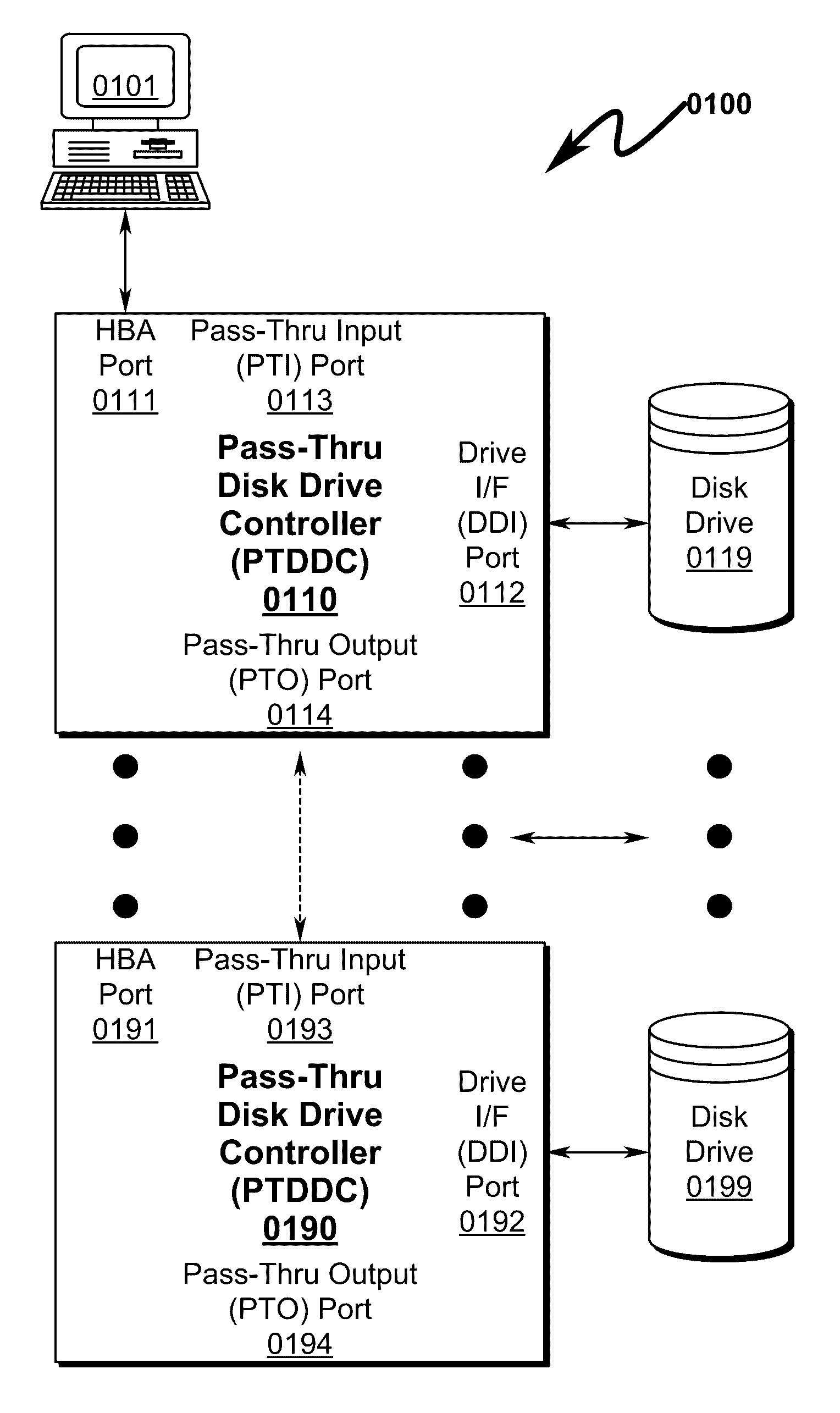
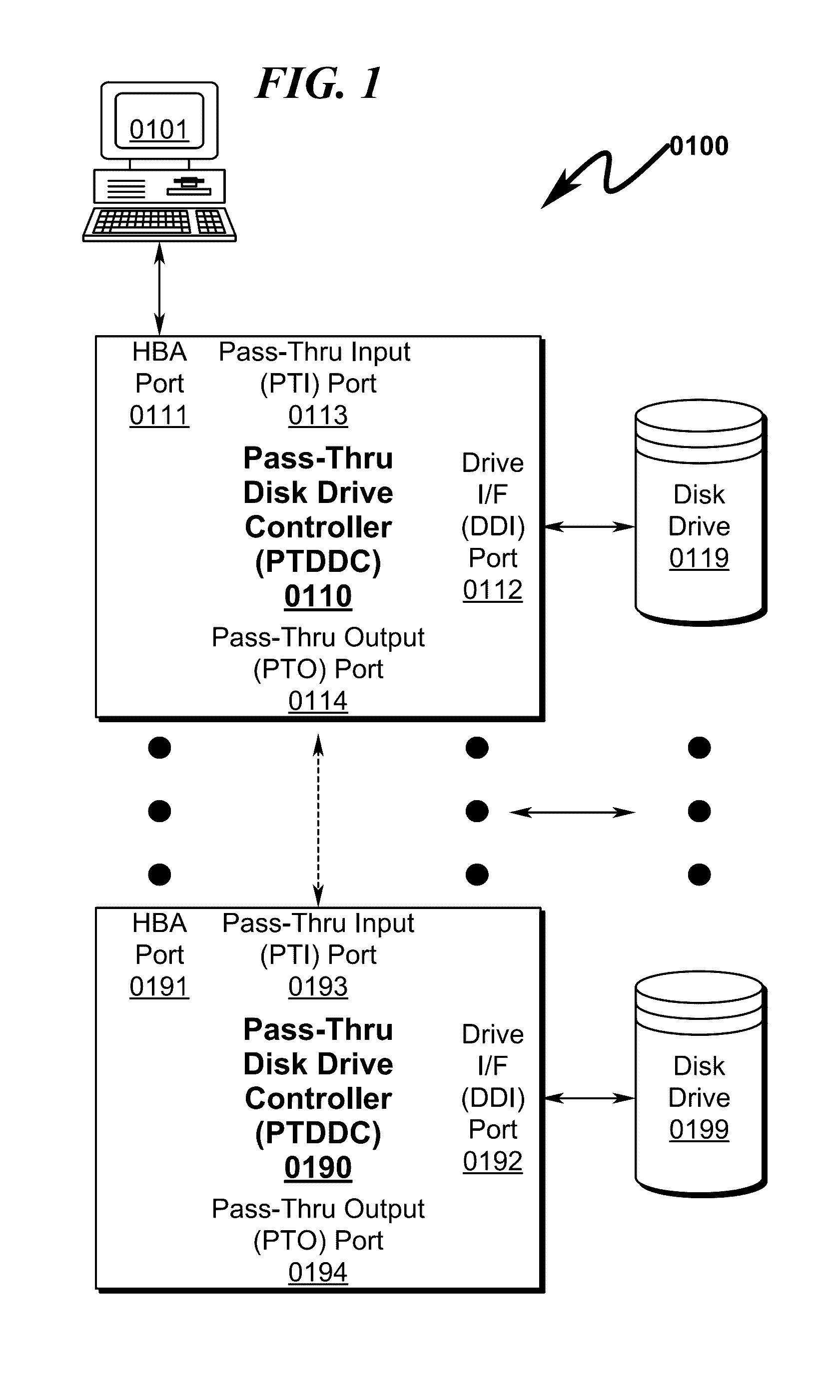
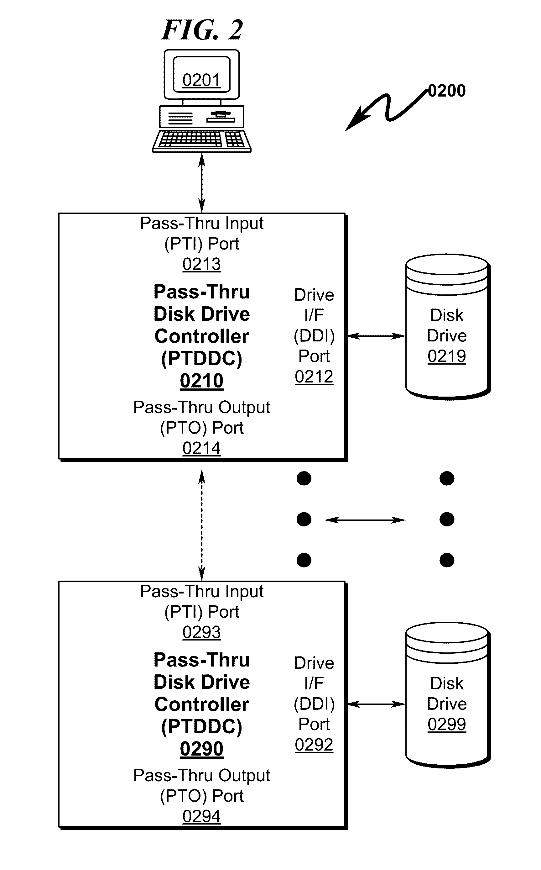
[0034]As an example, PTDDC daisy-chain incorporating two 1 TB disk drives in a daisy-chain configuration may be configured with 1000 TB (1 PB) of virtual storage and thus have 2 TB of actual physical storage and 998 TB of phantom storage. Hardware logic within the PTDDC chain will provide actual physical storage for the low LBA addresses of the virtual address space and actual physical storage for the highest LBA addresses of the virtual address space on one or both of the 1 TB disk drives. This hardware mapping ensures that when the NTFS file system is created by the MICROSOFT® or other operating system that the secondary (backup) GPT can be created without incurring a write failure by the operating system. In this context, while the

Problems solved by technology

Thus, for a petabyte-class (1000 terabyte) storage array, implementation costs typically range from USD$1M-USD$3M, when the drive costs would be approximately USD$25000, meaning that interconnect costs in typical server arrays consume approximately 98% of the cost of the storage array.
Thus, in commercial storage array systems, interconnect costs (rather than storage costs) dominate the cost profile of the overall system.
It should be noted within the following discussion that while some operating systems provide capabilities to link multiple disk drives together to form larger logical volumes, to date operating systems do not provide provisions for “holes” in the logical address space of a disk drive other than to provide for “bad” blocks on the disk drive that are mapped as unusable.
Furthermore, it sh

Method used


Image

  • Raid hot spare system and method
  • Raid hot spare system and method
  • Raid hot spare system and method

Examples


Embodiment Construction

[0100]While this invention is susceptible of embodiment in many different forms, there is shown in the drawings and will herein be described in detailed preferred embodiment of the invention with the understanding that the present disclosure is to be considered as an exemplification of the principles of the invention and is not intended to limit the broad aspect of the invention to the embodiment illustrated.

[0101]The numerous innovative teachings of the present application will be described with particular reference to the presently preferred embodiment, wherein these innovative teachings are advantageously applied to the particular problems of a RAID HOT SPARE SYSTEM AND METHOD. However, it should be understood that this embodiment is only one example of the many advantageous uses of the innovative teachings herein. In general, statements made in the specification of the present application do not necessarily limit any of the various claimed inventions. Moreover, some statements m...


PUM


Abstract

A RAID (redundant array of independent disks) hot spare (RHS) system and method that permits a daisy-chain of interconnected pass-thru disk drive controllers (PTDDCs) each connected to a SATA local disk drive (LDD) storage element (DSE) to support a hot spare disk (HSD) such that a failing disk drive (FDD) in the RAID array can be immediately replaced by a HSD within the PTDDC daisy-chain without operator intervention is disclosed. The PTDDCs within the daisy-chain are configured in RAID fashion to support mirroring of one or more drives in the PTDDC daisy-chain. The PTDDCs monitor functional status of LDDs attached to each PTDDC. FDD failure triggers activation of a HSD in the PTDDC daisy-chain and automatic mirror copying along the PTDDC daisy-chain of RAID data from a master disk drive (MDD) mirrored to the LDD. FDD-PTDDC and HSD-PTDDC LBA mapping registers are updated after mirror copying completes.

Description

CROSS REFERENCE TO RELATED APPLICATIONS[0001]This application is a Continuation-In-Part (CIP) patent application of and incorporates by reference U.S. Utility patent application for FILE SYSTEM EXTENSION SYSTEM AND METHOD by inventor Kevin Mark Klughart, filed with the USPTO on Oct. 19, 2015, with Ser. No. 14 / 886,616, EFSID 23823476, confirmation number 8917, docket AZKMK.0103CIP4, and issued as U.S. Pat. No. 9,460,110 on Oct. 4, 2016.[0002]Application Ser. No. 14 / 886,616 is a Continuation-In-Part (CIP) patent application of and incorporates by reference U.S. Utility patent application for DATA STORAGE RAID ARCHITECTURE EXTENSION SYSTEM AND METHOD by inventor Kevin Mark Klughart, filed with the USPTO on Apr. 13, 2015, with Ser. No. 14 / 685,439, EFSID 22049250, confirmation number 6962, docket AZKMK.0103CIP3, and issued as U.S. Pat. No. 9,164,946 on Oct. 20, 2015.[0003]Application Ser. No. 14 / 685,439 is a Continuation patent application (CPA) of and incorporates by reference U.S. Util...

Claims


Application Information

Patent Timeline
IPC IPC(8): G06F11/20G06F3/06
CPCG06F11/2038G06F11/2058G06F11/2069G06F3/0689G06F13/4247G06F3/0665G06F3/0607G06F13/409G06F3/0619G06F3/0658G06F2213/0032G06F2213/3802G06F2213/28G06F11/1662G06F11/2094G06F16/183
Inventor KLUGHART, KEVIN MARK
Owner KLUGHART KEVIN MARK
Why Eureka
Try Eureka