Independent control of auger and hopper assembly in electric blender system

a technology of electric blender and hopper assembly, which is applied in the direction of positive displacement liquid engine, sold ingredients supply apparatus, and wellbore/well accessories, etc., can solve the problems of too late to reposition the blender unit trailer, the hopper associated with the blender unit can be difficult to align with the proppant feed, and the conveyor is difficult to tell when the trailer is properly aligned

Active Publication Date: 2017-02-02
US WELL SERVICS LLC
View PDF19 Cites 65 Cited by
  • Summary
  • Abstract
  • Description
  • Claims
  • Application Information

AI Technical Summary

Benefits of technology

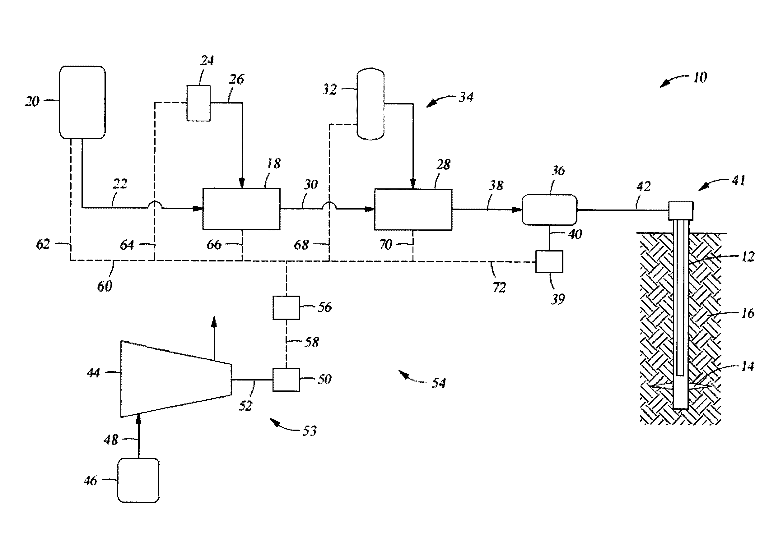
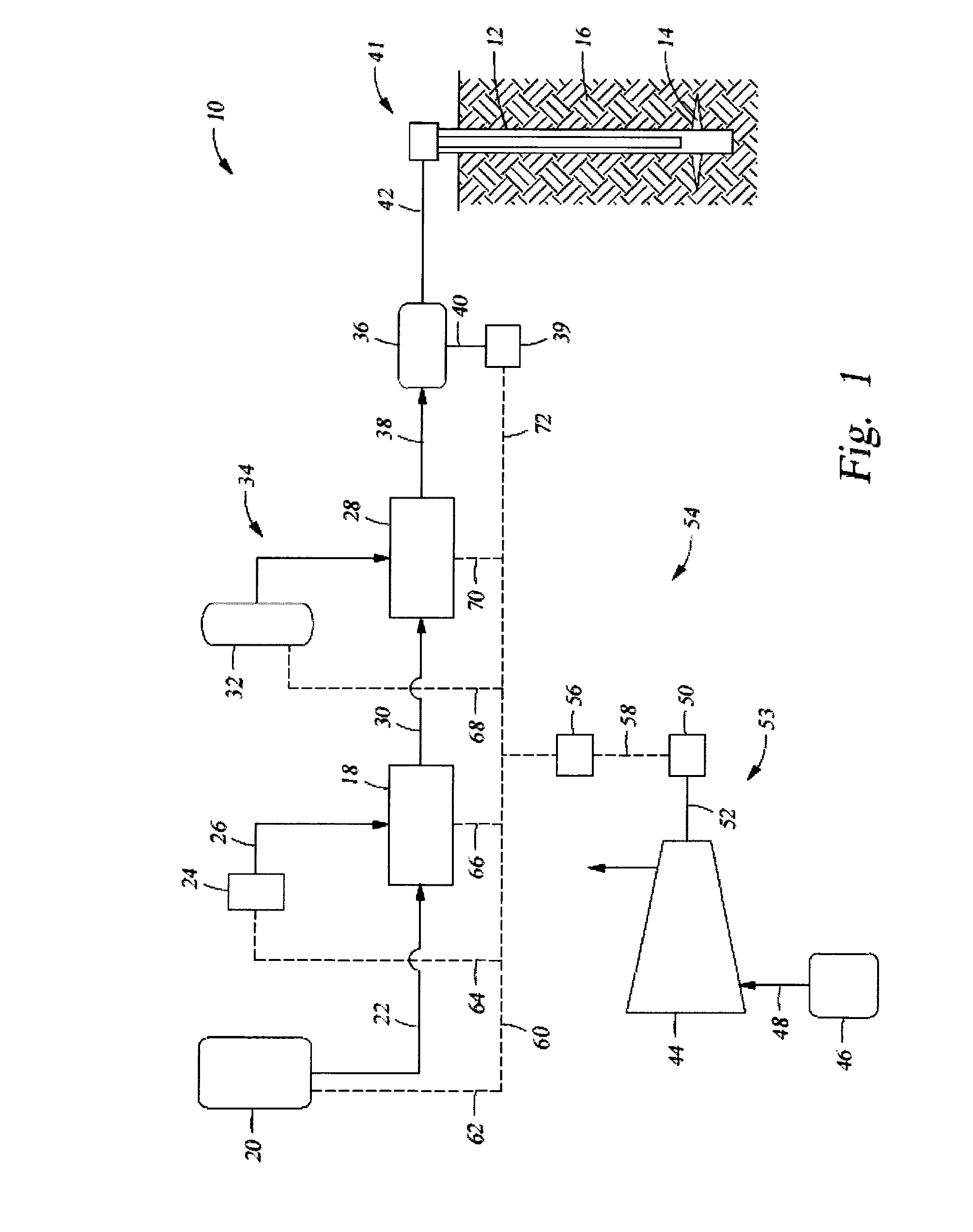
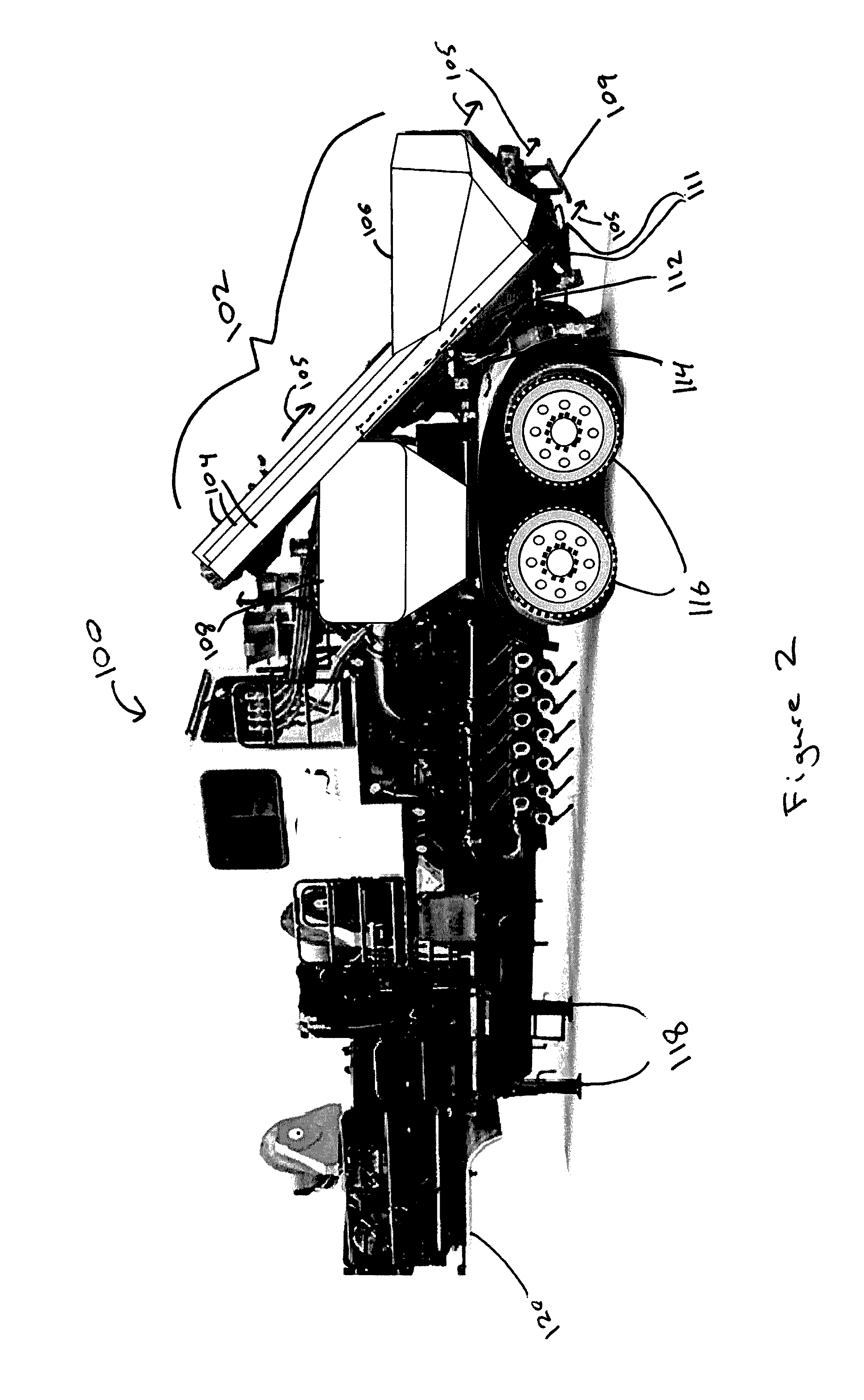
[0011]Methods according to various embodiments can include positioning a blender unit near a proppant source. The blender unit can be mobile. For example, it can be positioned on a truck or trailer that includes various other components of a blender system, such as a blender tub with an upper opening, and an auger and hopper assembly with the hopper having an upper opening and the auger outlets being positioned above the center of the blender tub. An example method can further include deploying the auger and hopper assembly from a stowed position to a deployed position. When the assembly is in the deployed position, the hopper will be aligned with a proppant feed from the proppant source. For example, the proppant can be fracturing sand, and the proppant feed can be a sand conveyor configured to deliver sand to the hopper. Deploying the assembly, according to various embodiments, includes powering one or more actuators with a battery. In addition, the blender unit can be connected to a power supply, which is independent from the battery that powers the actuators of the auger and hopper assembly.
[0012]When the auger and hopper assembly is moved to the deployed position, proppant from the proppant feed can be received into the hopper through the upper opening of the hopper. One or more augers with inlets positioned to receive proppant from the hopper can move proppant out of the hopper. The auger outlets are positioned above the blender tub when the auger and hopper assembly is in the deployed position. Proppant from the hopper can then be released via the auger outlets into the blender tub, where it is received by the blending unit. The blending unit can then mix the proppant with a fluid to prepare a fracturing slurry. This slurry can be pumped to a fracturing pump system, where it can be highly pressurized and pumped into a subterranean formation, as discussed in more detail below.

Problems solved by technology

The hopper associated with the blender unit can be difficult to align with the proppant feed.
This difficulty arises, in part, because during transport on a trailer, the hopper of the blender unit is typically placed in a raised position.
The problem lies in the necessary order of these three steps in known systems.
The problem with this is that when in the hopper is in the elevated position, it is very difficult to tell when the trailer is properly aligned with the conveyor.
Furthermore, by the time power is connected, allowing the hopper to be lowered, it is too late to reposition the blender unit trailer if the hopper does not properly align with the conveyor.

Method used


Image

  • Independent control of auger and hopper assembly in electric blender system
  • Independent control of auger and hopper assembly in electric blender system
  • Independent control of auger and hopper assembly in electric blender system

Examples


Embodiment Construction

[0022]The method and system of the present disclosure will now be described more fully hereinafter with reference to the accompanying drawings in which embodiments are shown. The method and system of the present disclosure may be in many different forms and should not be construed as limited to the illustrated embodiments set forth herein; rather, these embodiments are provided so that this disclosure will be thorough and complete, and will fully convey its scope to those skilled in the art. Like numbers refer to like elements throughout. In an embodiment, usage of the term “about” includes + / −5% of the cited magnitude. In an embodiment, usage of the term “substantially” includes + / −5% of the cited magnitude.

[0023]It is to be further understood that the scope of the present disclosure is not limited to the exact details of construction, operation, exact materials, or embodiments shown and described, as modifications and equivalents will be apparent to one skilled in the art. In the ...


PUM


Abstract

Embodiments relate to a hydraulic fracturing system that includes a blender unit. The system includes an auger and hopper assembly to receive proppant from a proppant source and feed the proppant to the blender unit for mixing with a fluid. A first power source is used to power the blender unit in order to mix the proppant with the fluid and prepare a fracturing slurry. A second power source independently powers the auger and hopper assembly in order to align the hopper of the auger and hopper assembly with a proppant feed from the proppant source. Thus, the auger and hopper assembly can be stowed or deployed without use of the first power source, which is the main power supply to the blender unit.

Description

CROSS REFERENCE TO RELATED APPLICATIONS[0001]This application claims priority to and the benefit of, co-pending U.S. Provisional Application Ser. No. 62 / 242,657, filed Oct. 16, 2015 and is a continuation-in-part of, and claims priority to and the benefit of co-pending U.S. patent application Ser. No. 15 / 202,085, filed Jul. 5, 2016, which claimed priority to and the benefit of Ser. No. 13 / 679,689, filed Nov. 16, 2012, which issued as U.S. Pat. No. 9,410,410 on Aug. 9, 2016; the full disclosures of which are hereby incorporated by reference herein for all purposes.BACKGROUND OF THE INVENTION[0002]1. Field of Invention[0003]The present disclosure relates to operations in a subterranean formation. In particular, the present disclosure relates to a hydraulic fracturing system.[0004]2. Description of Related Art[0005]Hydraulic fracturing is a technique used to stimulate production from some hydrocarbon producing wells. The technique usually involves injecting fluid into a wellbore at a pr...

Claims


Application Information

Patent Timeline
Patent Type & Authority Applications(United States)
IPC IPC(8): B01F15/02B01F15/00
CPCB01F15/0235B01F15/00538B01F2215/0081E21B43/26E21B43/267B01F15/00519F04B17/03F04B19/22F04B49/20F04B17/06F04B23/00F04B47/02F04B49/065B28C9/04B28C7/0477B28C7/10B01F35/71731B01F35/3204B01F35/32025B01F2101/49E21B43/2607
Inventor OEHRING, JAREDHINDERLITER, BRANDON N.
Owner US WELL SERVICS LLC
Why Eureka
Try Eureka