Display for hand-held electronics

a handheld electronic and display technology, applied in the field of displays, can solve problems such as power cable management problems for the average salesperson, complicated situation in a retail store, and cable tangling problems

Active Publication Date: 2017-02-02
MOBILE TECH
View PDF4 Cites 37 Cited by
  • Summary
  • Abstract
  • Description
  • Claims
  • Application Information

AI Technical Summary

Benefits of technology

[0050]As indicated above, prior art displays have relied on multi-conductor cables that are included as part of a reel assembly for providing both electrical power and electrical security signals to the mounting or puck. In other words, the retractor carries one pair of wires for a power circuit that is connected to the power jack of the hand-held and a separate pair of wires for a security circuit that drives security sensors in the puck, or a secondary security cable, or both things at the same time. The advantage of the present invention is that only one power source or circuit from below the countertop is needed in order to drive both the power and security functions emanating from the puck position. Moreover, because power can be supplied when the puck is at “rest,” and there is no need for under-the-counter power supply in “lift” mode, the need to use multi-conductor retractors is eliminated. Instead, mechanical retractors with steel cables can be used.

Problems solved by technology

Security against theft was the primary issue, at the time, rather than supplying operating power to the device.
Because of the large numbers of devices mounted on the modern display, tethering each one creates a cable tangling problem.
Other related problems developed, at the time, involving the burdens imposed on the local salesperson who needed to make power supply changes at the display when new hand-held models were swapped out with old ones, or the retailer changed its mix of brands offered for sale.
Swapping different hand-held models to and from many post positions creates a power cable management problem for the average salesperson, particularly when different hand-helds with different power fittings and voltage requirements are swapped to and from the same post position.
It creates a very complex situation in a retail store as inventory rotates.
However, Burke '906 was not marketable because it relies on mechanical “pin” connections to plug into specific line voltages offered by the retractor cable—that is, it had no easy way of adapting if new devices came onto the market that needed other operating voltages.
However, while Burke '906 and MTI's early design provided different ways to deal with power supply issues for swapping out hand-helds on the display, they shared some similar technical problems that are associated with multi-conductor retractors.
This issue related to “physical” security in that retailers want hand-helds to be tethered to the display in a way that makes it difficult to physically remove the hand-held regardless of whether or how many electrical security sensors are used.
However, the tether is not as physically secure as the steel cable tethers that were used in the retail industry in earlier years, before the advent of electrical security sensors, like Leyden '807.
Steel cable tethers fell out of use in the display industry because, obviously, they lack wiring and, therefore, the ability to conduct power and security signals to the mounting puck position.
Another problem with multi-conductor retractors lies in the wear and tear these retractors undergo during the repeated cycling that occurs as the consumer lifts and returns the puck to its original position on the display.
Because the retractors are generally low voltage systems, the mechanical wear and tear sometimes alters the voltage transmitted through the wires or causes short circuits.
While less of a problem today compared to ten years ago, at one point in time in the development of these products, mounted hand-helds were sensitive to relatively small voltage fluctuations in the power supply.
All of the above represents a variety of technical issues that have gone hand-in-hand with the evolution of the consumer hand-held market and the retailer's need to display powered-up products in an attractive way, while still maintaining theft against security.

Method used


Image

  • Display for hand-held electronics
  • Display for hand-held electronics
  • Display for hand-held electronics

Examples


Embodiment Construction

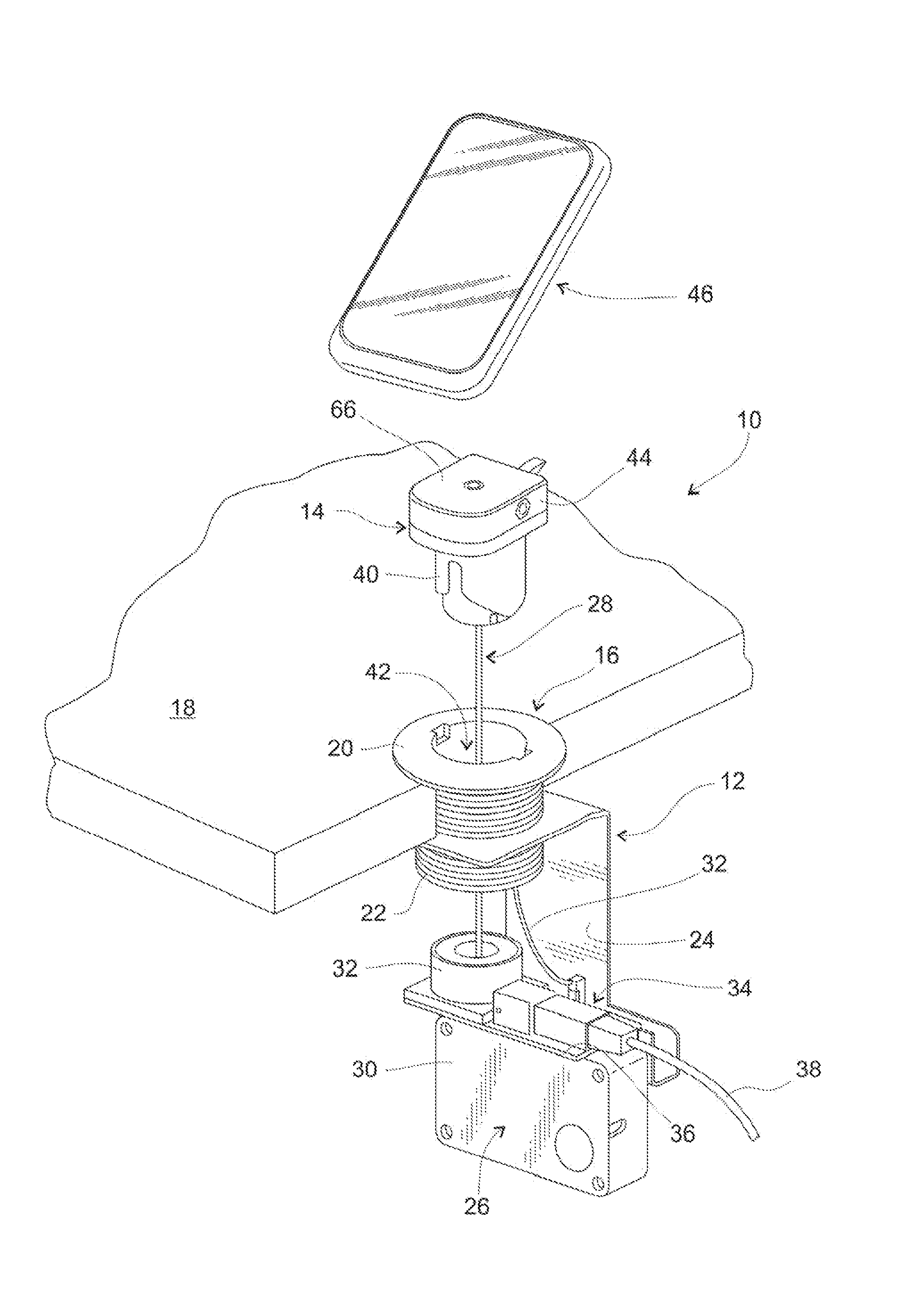
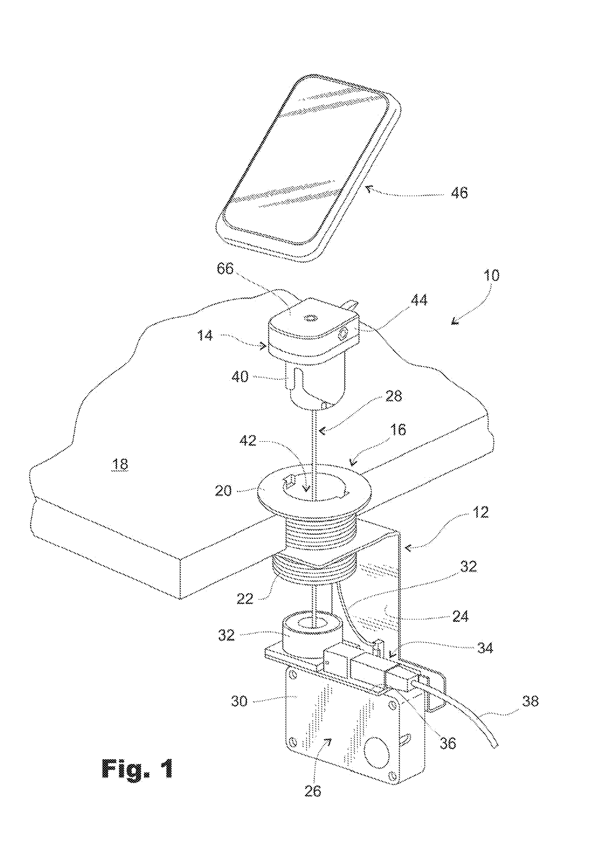
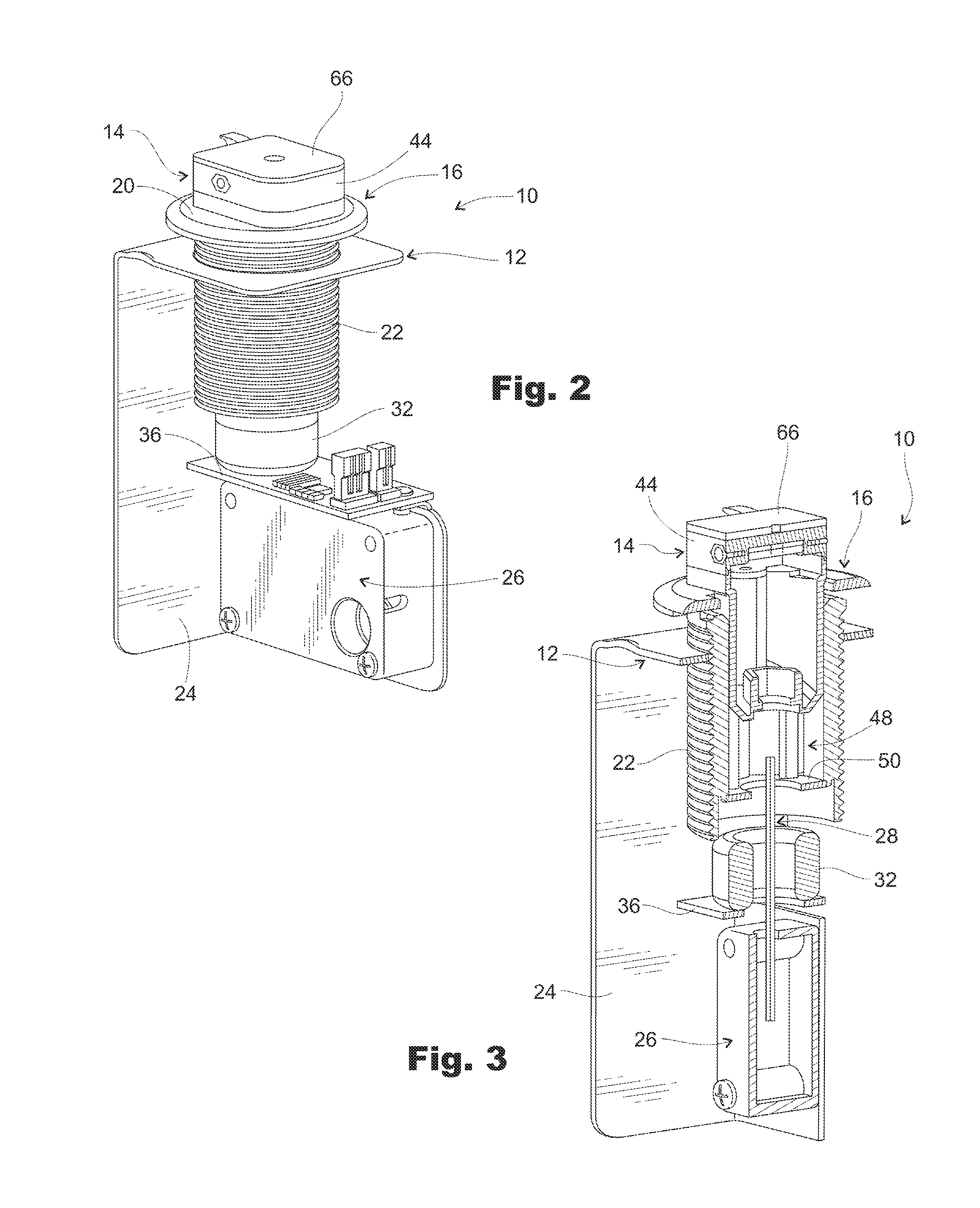
[0104]In the drawings, and referring first to FIG. 1, shown generally at 10 is an improved display post assembly constructed in accordance with the various design improvements described and claimed here. The post assembly 10 includes a base assembly portion (indicated generally at 12) and a puck assembly portion (indicated generally at 14).

[0105]First, beginning with base assembly 12, the display post 10 includes a base assembly portion or fitting 16 that is mounted to a display countertop surface 18. The base portion 16 has an annular flange 20 that rests on top of surface 18. Extending downwardly from the annular flange 20 is a threaded portion 22 that carries a bracket 24. The bracket 24 further carries a mechanical retractor (indicated generally at 26).

[0106]The mechanical retractor 26 is conventional in design and includes a spring-loaded steel cable (indicated generally at 28), the length of which is drawn from and returned to the retractor housing 30 as the puck assembly 14 i...


PUM


Abstract

The invention disclosed here is a display system for managing power and security for a plurality of hand-held electronic devices sold to consumers in a retail location. The display includes features that allow power to be supplied to individual devices and security sensors without continuous hard wiring or multi-conductor retractor cables. The display also allows for individual security alarms to be triggered when a theft occurs. Security alarm conditions are preferably triggered via wireless signals.

Description

TECHNICAL FIELD[0001]The invention described here relates to displays that are designed to provide operating power and security against theft for hand-held electronics that are offered for sale in a retail setting.BACKGROUND OF THE INVENTION[0002]The business of building and servicing retail displays for hand-held electronics has developed into a sophisticated industry. “Big Box” and other large electronics retailers are the major industry customers. The typical display is a countertop-style display that involves a large number of hand-held electronic devices mounted to the countertop via posts or similar kinds of mounting structures.[0003]Mr. Roger Leyden was an early inventor of countertop display assemblies that were initially used to mount film cameras in a retail location. U.S. Pat. No. 5,861,807 (“Leyden '807”) is typical and describes a mounting body that carries a camera. The mounting body is lifted from a pedestal or similar support so that the camera can be examined by a p...

Claims


Application Information

Patent Timeline
Patent Type & Authority Applications(United States)
IPC IPC(8): G08B13/14G08B25/10
CPCG08B25/10G08B13/1463G08B13/1454G08B13/1472G08B17/06G08B13/1445
Inventor HENSON, DONALDALLISON, THAINEGOLDBERG, JASONOLSON, JUSTINPITT, ERICSCHATZ, KRISWHEELER, WADE
Owner MOBILE TECH
Why Eureka
Try Eureka