A magnetic proximity switch

a proximity switch and magnetic technology, applied in the field of new magnetic proximity switches, can solve the problems of reduced elastic force, frequent arcing, slow springing back motion, etc., and achieve the effect of simplifying the device's assembly, avoiding metal fatigue, and simplifying the internal structur

Active Publication Date: 2017-02-02
FOSHAN CHUANDONG MAGNETOELECTRICITY
View PDF3 Cites 1 Cited by
  • Summary
  • Abstract
  • Description
  • Claims
  • Application Information

AI Technical Summary

Benefits of technology

[0005]The purpose of the present invention is to overcome the shortcomings of the prior art and provide a new magnetic proximity switch, strengthening the instantaneous acting force when the contact point is open or closed. Additionally, the present invention has a smaller movement angle, which can effectively relieve the metal fatigue and solve the arcing problem caused by long-term use that frequently occurs in the prior art.
[0016]In the present invention, the moving magnet moves downwards under the action of the external magnet so as to press the elastic tongue piece through the assistant portion until the moving contact and the static contact are closed. After eliminating the acting force of the external magnet, the moving contact and the static contact can recover under the action of the elastic tongue piece. Compared with the prior art, the present invention has the following advantages: firstly, the present invention has a limiting mechanism, which can effectively confine the assistant portion's upward and downward action, avoiding the metal fatigue caused by an excessive moving range of the elastic tongue piece and solving the arcing problem produced by long-term use. Second, the cooperation of the elastic piece and the elastic tongue piece of the present invention significantly simplifies the internal structure, simplifying the device's assembly and reducing the manufacturing cost. Additionally, the reasonable design of the structure also prolongs the product's lifespan and greatly extends the application fields of the present invention.

Problems solved by technology

In the prior art, the reset mechanism of the magnetic proximity switch is comprised of the tension spring components, which have the following disadvantages: firstly, after being in use for a long time, the elastic force can be reduced due to metal fatigue, resulting in a slow springing back motion, a reduced acting force and frequent arcing.
Second, the installation of the tension spring components requires more assistant parts, making the device's structure more complicated, having a difficult assembly and high manufacturing cost.
Third, in order to realize both switching-on and switching-off states, the tension spring may bear a relatively large stress in a normally-open state due to the long working distance, leading to the metal fatigue and decrease of the product's lifespan.
In conclusion, the shortcomings of the traditional magnetic proximity switch are urgent problems that need to be solved for those skilled in this field.

Method used


Image

  • A magnetic proximity switch
  • A magnetic proximity switch
  • A magnetic proximity switch

Examples


Embodiment Construction

[0028]Drawings and detailed embodiments are combined hereinafter to elaborate the technical principles of the present invention.

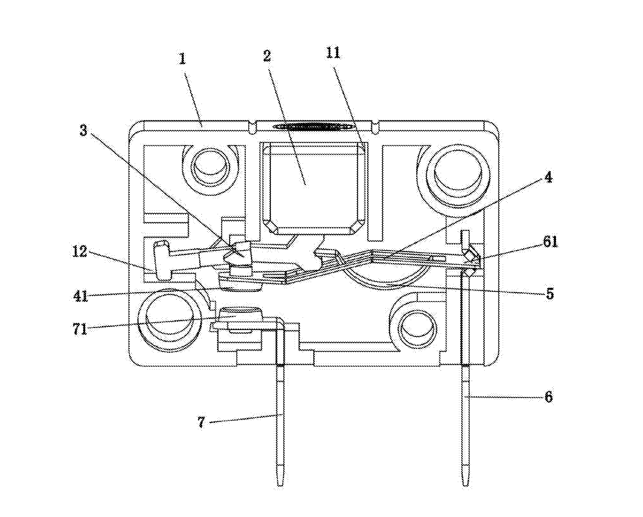
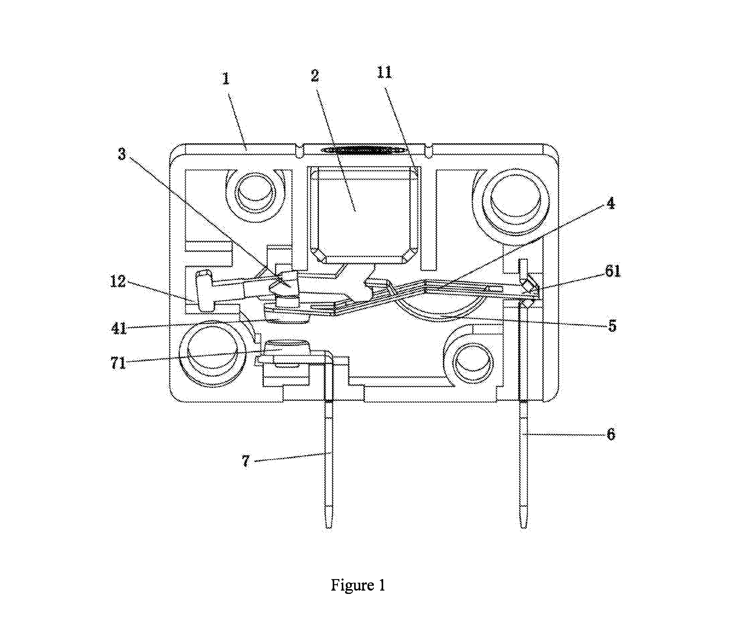
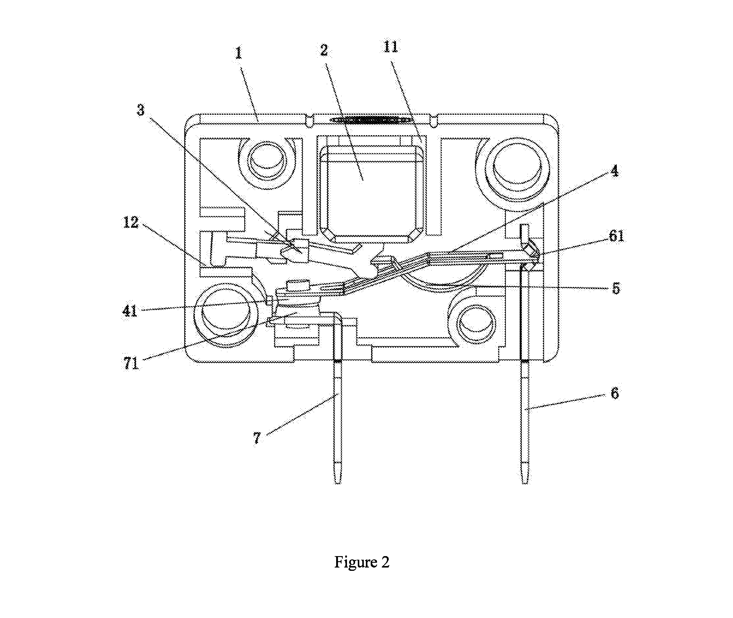
[0029]As shown in FIGS. 1-3, the new magnetic proximity switch of the present invention comprises a shell 1, wherein a moving magnet 2, which can move up and down, is disposed on the upper part in the shell 1. Specifically, a sliding groove 11 is disposed in the shell 1, and the moving magnet 2, which can move up and down, is disposed in the sliding groove 11. A sliding track is disposed in the sliding groove 11, and the moving magnet 2 is disposed on the sliding track, enabling the moving magnet 2 to move up and down more stably. The way in which the moving magnet 2 is disposed in the shell 1 is similar to the prior art, which is illustrated briefly herein.

[0030]A first terminal strip 6 and a second terminal strip 7 are fixedly provided left and right in parallel at the bottom in the shell 1. A static contact 71 is disposed on the upper end of the second t...


PUM


Abstract

This invention relates to a new magnetic proximity switch, comprising a shell, wherein a moving magnet that can move up and down is disposed on the upper part in the shell; a first terminal strip and a second terminal strip are fixedly disposed left and right in parallel at the bottom in the shell; a static contact is disposed on the second terminal strip; an elastic piece is disposed on the first terminal strip; a moving contact is disposed at the outer end of the elastic piece; an assistant rod is disposed at the middle part in the shell, an assistant portion is disposed at the inner end of the assistant rod, a limiting mechanism is disposed between the assistant rod and the shell, an elastic tongue piece is disposed on the elastic piece, and the outer end of the elastic tongue piece is disposed against the assistant portion.

Description

TECHNICAL FIELD OF THE INVENTION[0001]The present invention relates to the technical field of a proximity switch, and more particularly, to a new magnetic proximity switch.BACKGROUND OF THE INVENTION[0002]The magnetic proximity switch is a device capable of realizing the switching-on and switching-off functions through the interaction of the moving magnet, the static magnet and the external magnet, which are currently being widely used in many technical fields. The reasonableness of its structure can directly determine the quality and lifespan of the new magnetic proximity switch.[0003]In the prior art, the reset mechanism of the magnetic proximity switch is comprised of the tension spring components, which have the following disadvantages: firstly, after being in use for a long time, the elastic force can be reduced due to metal fatigue, resulting in a slow springing back motion, a reduced acting force and frequent arcing. Second, the installation of the tension spring components r...

Claims


Application Information

Patent Timeline
Patent Type & Authority Applications(United States)
IPC IPC(8): H01H5/18H01H33/04H01H36/00
CPCH01H5/18H01H33/04H01H36/00H01H5/22H01H36/0006
Inventor LONG, KEWENYAO, TIANBOAO
Owner FOSHAN CHUANDONG MAGNETOELECTRICITY
Why Eureka
Try Eureka