Mobile Terminal

a mobile terminal and terminal technology, applied in the direction of antennas, antenna details, electrical devices, etc., can solve the problem of hard to meet the communication demands of mobile terminals

Inactive Publication Date: 2017-02-02
AAC TECH PTE LTD
View PDF11 Cites 12 Cited by
  • Summary
  • Abstract
  • Description
  • Claims
  • Application Information

AI Technical Summary

Benefits of technology

[0019]LDS couples with the metal radiator. The generated high frequency resonance is 1710 MHz-2170 MHz and the generated low frequency resonance is 824 MHz-894 MHz. When circuit is on closing status, the antenna frequency band that antenna module 13 meet are low frequency 880 MHz-960 MHz and high frequency 2300 MHz-2690 MHz. The antenna module 13 can work under the following frequency bands through the controlling of the switching circuit. Low frequency 824 MHz-960 MHz and high frequency 1710 MHz-2690 MHz. While the high frequency bandwidth is widened, the performance of low frequency bandwidth is improved. The plan solves the wide frequency band design requirements of LTE antenna under the full metal machine body environment.
[0029]II. LDS antenna can work as one part of antenna. The resonance frequency can be adjusted through the adjustment of LDS pattern size. The way of adjusting is simple and reliability is strong.
[0009]FIG. 4 is a diagram (A) showing the antenna efficiency of the antenna module of the mobile terminal of the embodiment.
[0032]V. Controlling the connection status of LDS antenna through switching circuit can realize the design demands of wide band width required by high frequency and improve low frequency band width to certain degree too. The program can solve the design demands of high frequency and low frequency bandwidth of LTET antenna under the full metal machine body environment very well.

Problems solved by technology

Although this design solves the problem of radiation of antenna under metal environment, the shortcomings of bad performance of narrow high frequency band and wide low frequency band still exists, which is hard to satisfy with the communication demands of mobile terminal.

Method used


Image

  • Mobile Terminal
  • Mobile Terminal
  • Mobile Terminal

Examples


Embodiment Construction

[0011]The present invention will hereinafter be described in detail with reference to an exemplary embodiment. To make the technical problems to be solved, technical solutions and beneficial effects of present disclosure more apparent, the present disclosure is described in further detail together with the figures and the embodiment. It should be understood the specific embodiment described hereby is only to explain this disclosure, not intended to limit this disclosure.

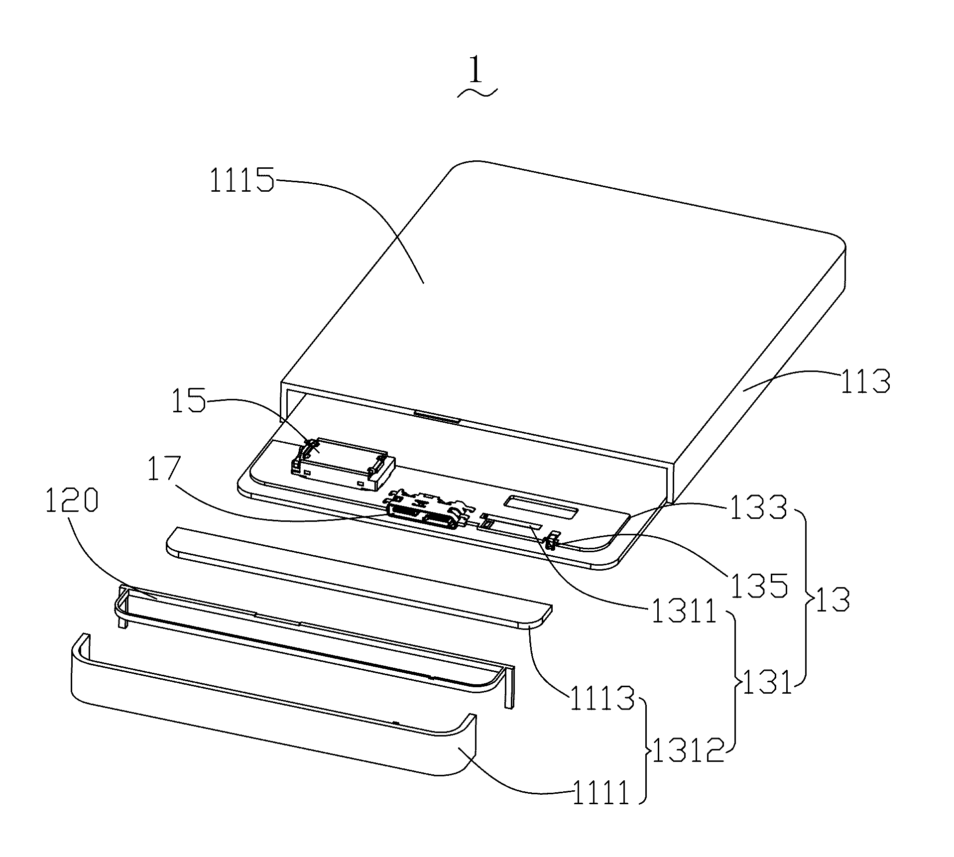
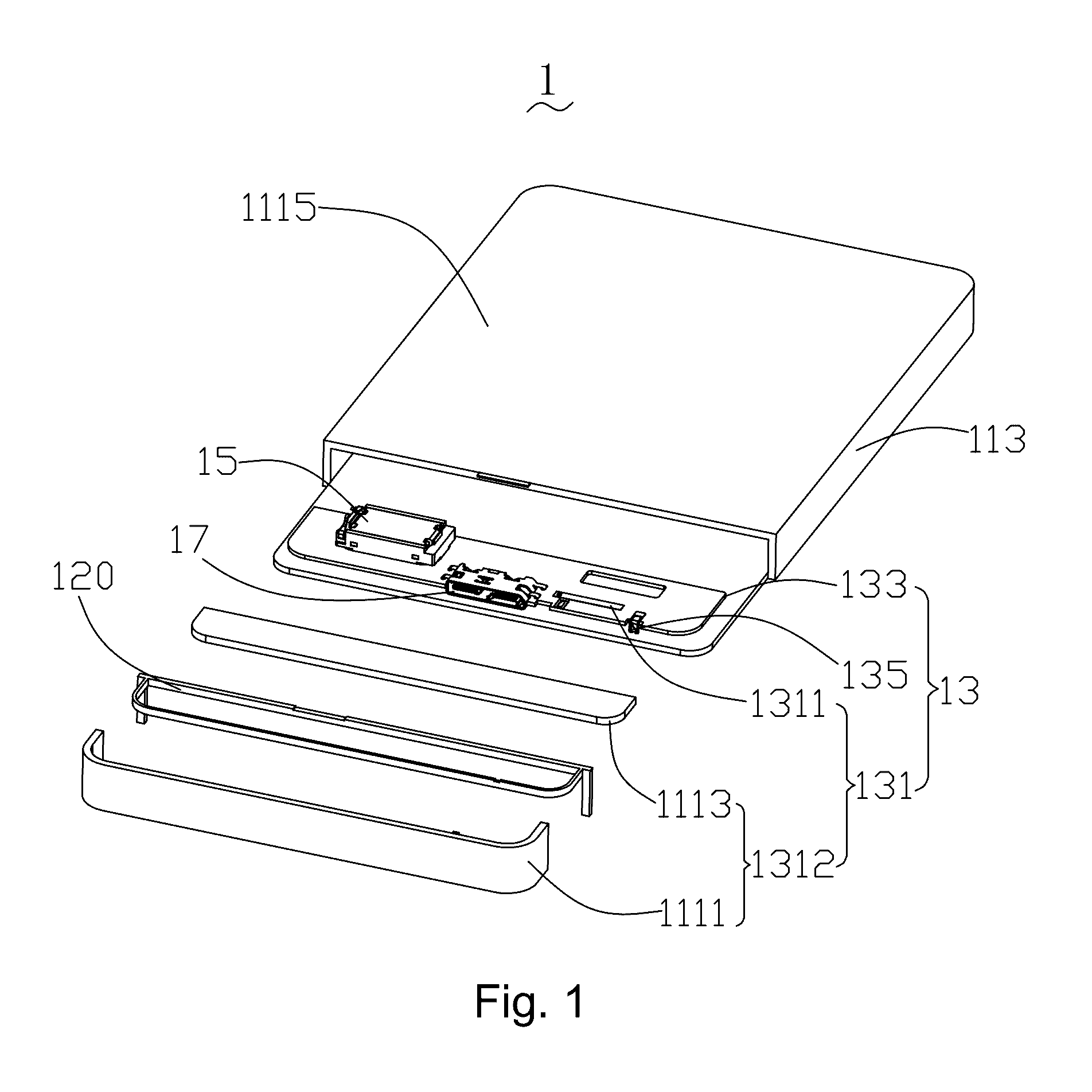
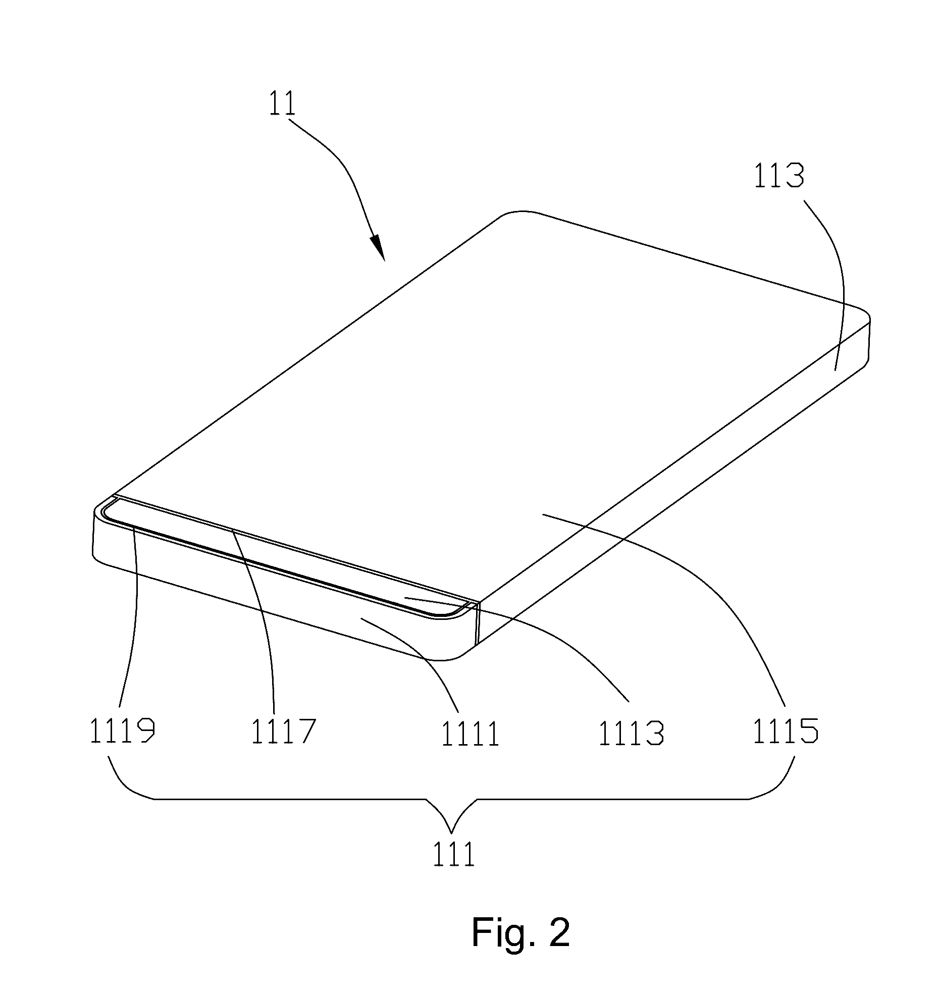
[0012]Referring to FIGS. 1-2, a mobile terminal in accordance with an exemplary embodiment of the present disclosure includes a metal shell. The mobile terminal 1 includes a metal housing 11 with an accommodation space, an antenna module 13, a loudspeaker 15 and a USB module 17. The antenna module 13, the loudspeaker 15 and the USB module 17 are received in the accommodation space.

[0013]The metal shell 11 includes a metal housing 111 and a metal frame 113. The metal housing 111 cooperates with the metal frame 113 for...


PUM


Abstract

A mobile terminal is disclosed. The mobile terminal includes a metal housing with an accommodation space, the metal shell including a metal housing having a metal cover, a metal ring disposed outside of the metal cover, and a metal rear housing; an antenna module received in the accommodation space. The antenna module includes a main board with a grounding terminal, the main board including a switching circuit connected with the grounding end of the main board electrically and an LDS antenna controlled by the switching circuit. The main board is connected with the metal cover and the metal ring electrically, the metal cover and the metal ring is coupled with the LDS antenna.

Description

FIELD OF THE INVENTION[0001]The present invention relates to mobile communication technology field.DESCRIPTION OF RELATED ART[0002]With the development of mobile communication technology, cell phone, PAD, laptop etc. gradually become the indispensable electronic products in life, and the antenna system is added for this kind of electronic product to make it become electronic communication product with communication function. But consumer is not only satisfied with the application function of the antenna system and but also puts forward requirements on the appearance. In order to pursue fashionable appearance molding, existing mobile terminal, especially the cell phone in mobile terminal, the cell phone molding of traditional plastic housing has not been satisfied by the demands of one part of medium-end and high-end personages. They have higher demands on the appearance of cell phone, so the cell phone with metal housing becomes one kind of trend. Relative to the housing of other ma...

Claims


Application Information

Patent Timeline
Patent Type & Authority Applications(United States)
IPC IPC(8): H01Q1/24
CPCH01Q1/241H01Q1/243
Inventor YAN, WEI
Owner AAC TECH PTE LTD
Why Eureka
Try Eureka